Shared posts

07 Aug 01:16

Ram ProMaster EV First Drive Review: Electric, but still a very van-y van

by Joel Stocksdale
04 Oct 03:54

Your Own Home IR Cloner

by Abe Connelly
Infrared controller and receiver board

Many devices use infrared (IR) as a signalling medium like, for example, RGB LED strip controllers
modules and some TV controllers. Often times these signals aren’t meant for secure applications which means the functionality can be reproduced by simply replaying back the received signal verbatim. Sometimes, enterprising hackers want to reverse engineer the IR signals, perhaps to automate some tasks or just to get a better understanding of the electronics we use in our everyday life. To help in this effort, [dilshan] creates an open source hardware IR cloner device, capable of snooping IR signals and retransmitting them.

The IR cloner is a sweet little IR tool that can be used to investigate all sorts of IR signals.
In addition to the source code and design files, [dilshan] has also taken care to create detailed documentation as an addendum to the video on assembly and usage.

Infrared transmitter/receiver cloner board with a 4x4 pushbutton board next to it and an EEPROM above them both

The IR cloner itself is a board that’s just over 41mm by 31mm with mixed surface mount and through hole components. The device has an LD271 IR LED that can transmit in the 880nm to 950nm range with a TSOP181 IR receiver that can receive in the same range. The STM8S003F3 microcontroller sits at the heart of the device. Depending on jumpers, wiring and battery connections, the device can take an external battery pack ranging from 3V or 5V to 9V. The board has an eight pin DIP that is meant to seat a 24LC32 32kbit EEPROM. Header pins are available to attach to an 4×4 pushbutton matrix that is meant to control the unit.

The main workflow looks to be setting the functional mode with the 4×4 pushbutton matrix with the EEPROM acting as storage. The signals can be replayed directly after receipt or can be analyzed more in depth by removing the EEPROM and downloading the saved signal data. [dilshan] recommends using something like an CH341A based programmer to read stored values from the EEPROM.

Having the IR cloner around would be the perfect tool to not only help reverse engineer something like a PixMob wearable LED wristband or an IKEA LED lamp but to use and hack on them yourself.

06 Sep 20:20

Stable Diffusion And Why It Matters

by Matthew Carlson

You might not have heard about Stable Diffusion. As of writing this article, it’s less than a few weeks old. Perhaps you’ve heard about it and some of the hubbub around it. It is an AI model that can generate images based on a text prompt or an input image. Why is it important, how do you use it, and why should you care?

This year we have seen several image generation AIs such as Dall-e 2, Imagen, and even Craiyon. Nvidia’s Canvas AI allows someone to create a crude image with various colors representing different elements, such as mountains or water. Canvas can transform it into a beautiful landscape. What makes Stable Diffusion special? For starters, it is open source under the Creative ML OpenRAIL-M license, which is relatively permissive. Additionally, you can run Stable Diffusion (SD) on your computer rather than via the cloud, accessed by a website or API. They recommend a 3xxx series NVIDIA GPU with at least 6GB of RAM to get decent results. But due to its open-source nature, patches and tweaks enable it to be CPU only, AMD powered, or even Mac friendly.

This touches on the more important thing about SD. The community and energy around it. There are dozens of repos with different features, web UIs, and optimizations. People are training new models or fine-tuning models to generate different styles of content better. There are plugins to Photoshop and Krita. Other models are incorporated into the flow, such as image upscaling or face correction. The speed at which this has come into existence is dizzying. Right now, it’s a bit of the wild west.

How do you use it?

After playing with SD on our home desktop and fiddling around with a few of the repos, we can confidently say that SD isn’t as good as Dall-E 2 when it comes to generating abstract concepts.

Boston Terrier with a mermaid tail, at the bottom of the ocean, dramatic, digital art.
Images generated by Nir Barazida

That doesn’t make it any less incredible. Many of the incredible examples you see online are cherry-picked, but the fact that you can fire up your desktop with a low-end RTX 3060 and crank out a new image every 13 seconds is mind-blowing. Step away for a glass of water, and you have ~15 images to sift through when you come back. Many of them are decent and can be iterated on (more on that later).

If you’re interested in playing around with it, go to huggingface, dreamstudio.ai, or Google collab and use their web-based interface (all currently free). Or follow a guide and get it set up on your machine (any guide we write here will be woefully out of date within a few weeks).

The real magic of SD and other image generation is human and computer interaction. Don’t think of this as a “put in a thing, get a new thing out”; the system can loop back on itself. [Andrew] recently did this, starting with a very simple drawing of Seattle. He fed this image into SD, asking for “Digital fantasy painting of the Seattle city skyline. Vibrant fall trees in the foreground. Space Needle visible. Mount Rainier in background. Highly detailed.”

Andy's drawing on the left, SD on the right

Hopefully, you can tell which one [Andrew] drew and which one SD generated. He fed this image back in, changing it to have a post-apocalyptic vibe. He then draws in a simple spaceship in the sky and asks SD to turn it into a beautiful spaceship, and after a few passes, it fits into the scene beautifully. Adding birds and a low-strength pass brings it together in a gorgeous scene.

SD struggles with consistency between generation passes, as [Karen Cheng] demonstrates in her attempt to change a video of someone walking to have a different outfit. She combines the output of Dalle (SD should work just fine here) with EBSynth, an AI good at taking one modified image and extrapolating how it should apply to subsequent frames. The results are incredible.

Ultimately, this will be another tool to express ideas faster and in more accessible ways. While what SD generates might not be used as final assets, it could be used to generate textures in a prototype game. Or generate a logo for an open-source project.

Why should you care?

Generated by Author via SD

Hopefully, you can see how exciting and powerful SD and its accompanying cousin models are. If a movie had contained some of the demos above just a few years ago, we likely would have called out the movie for being Hollywood magic.

Time will tell whether we will continue to iterate on the idea or move on to more powerful techniques. But there are already efforts to train larger models with tweaks to understand the world and the prompts better.

Open-source is also a bit of a double-edged sword, as anyone can take it and do whatever they want. The license on the model forbids its use for many nefarious purposes, but at this point, we don’t know what sort of ramifications it will have long term. Looking ten or fifteen years down the road becomes very murky as it is hard to imagine what could be done with a version that was 10x better and ran in real-time.

We’ve written about how Dall-E impacts photography, but this just scratches the surface. So much more is possible, and we’re excited to see what happens. All we can say is it is satisfying looking at a picture that makes you happy and knowing it was generated on your computer.

24 Mar 04:23

Finally, A Mapping Tool For Addressable LED Strings

by Lewin Day

Addressable LED strings have made it easier than ever to build fun glowable projects with all kinds of exciting animations. However, if you’re not going with a simple grid layout, it can be a little difficult to map your strings out in code. Fear not, for [Jason Coon] has provided a tool to help out with just that!

[Jason]’s web app, accessible here. is used for mapping out irregular layouts when working with addressable LED strings like the WS2812B and others that work with libraries like FastLED and Pixelblaze. If you’re making some kind of LED globe, crazy LED tree, or other non-gridular shape, this tool can help.

The first step is to create a layout of your LEDs in a Google Sheets table, which can then be pasted into the web app. Then, the app handles generating the necessary code to address the LEDs in an order corresponding to the physical layout.

[Jason] does a great job of explaining how the tool works, and demonstrates it working with a bowtie-like serpentine layout with rainbow animations. The tool can even provide visual previews of the layout so you can verify what you’ve typed in makes sense.

It’s a great tool that we recently saw put to use on [Geeky Faye’s] excellent necklace project. Video after the break.


18 Mar 04:44

50 of the Best Cult Classic Movies Released This Century

by Ross Johnson

What defines a “cult classic” film? Unfortunately, there exists no cohesive, comprehensive, widely recognized definition that can be used to classify a film as either undeniably cult, or undeniably not. It’s all far too slippery.

Read more...

18 Mar 02:05

Relive Your Glory Days With These Retro TV Sites

by Jake Peterson

The TV of today is fundamentally different from even its relatively recent past. Sure, cable still exists, but broadcast TV is increasingly an afterthought and those times when everyone seems to be watching the same show are fewer and farther between. You’re streaming something on HBO, I’m binging a season of one of…

Read more...

12 Jan 21:28

The Foo Fighters' Horror Comedy Actually Looks Rather Fun

by Germain Lussier

Say the name “Dave Grohl” and you think about rock. Nirvana. Foo Fighters. An all-time legend already and he’s still making music. Along his musical journey, Grohl has also more than dabbled in film, including directing one himself, the documentary Sound City, and appearing in movies such as Bill and Ted Face the Music

Read more...

16 Sep 21:38

Hoonigan brings the Warthog from Halo to life with 1,060 horsepower

by Joel Stocksdale
05 Aug 03:24

Dedicated LED Animation Framework For ESP32

by Danie Conradie

[Eric Arcana] has been creating animated holiday decorations for several years, which involved a lot of custom code to make things light up the way he wanted, pulling the microcontroller to make changes. Using ESP32s with remote software updates is easier, but [Eric] also wanted to make the code simpler. To achieve this he created Fade, a custom programming language/framework for controlling LED animations from the ESP32.

Fade is written for addressable RGB LEDs like the Neopixel/WS2812. It keeps track of the current color of every LED in the system and allows the user to define what color it should be at a specified time in the future. Time is specified using 10 ms clock cycles. The LEDs will smoothly change from one color to the other in the specified number of clock cycles, without needing to specify what the intermediate colors should be.

Code is written in simple IDE, running on a web server on the ESP32 itself, or on a remote Windows PC. The language is very simple, but still powerful enough to create complex LED animations. A key part of it is the ability to specify multiple concurrent state changes in just a few lines of code. [Eric] also included optioning to take touch button inputs and use them to update the animations. Another nice feature is a simulation window on the desktop IDE. It allows you to create custom LED layouts on PC, and test your code without needing to send it to the ESP32.

Addressable LEDs have made creating large LED installations a lot simpler, like this 6 foot LED ball or a LED Video Wall.

22 Jul 04:15

The Essential Guide to Prototyping your Electronic Hardware Product

by Hailey Blessing

For the next few weeks, John Teel, Founder of Predictable Designs, will be sharing a series of guest blog posts with us, helping readers gain insights into strategy, design thinking, and how to get great product ideas to market. John is an electronics design engineer, serial entrepreneur and blogger, who now focuses on helping hardware entrepreneurs, startups and small companies through his Hardware Academy program. Check out his website for more insights and to learn more.


A new consumer product will go through many prototype iterations before being ready for mass manufacturing. In this article I will teach you exactly what you should be learning with each and every prototype version. Each stage of bringing your electronic product to market will have different prototype requirements. Unfortunately, no single prototype is sufficient for bringing a commercial product all the way to market. No matter how advanced computer-aided design has become, your new product will need multiple prototype iterations before being ready for mass manufacturing.

Prototyping your product is all about learning. Each time you create a prototype version you will, or at least should, learn something new. Always start with the simplest, cheapest way to prototype your product. Then, with each prototype iteration you should progress closer and closer to a production-quality prototype. During the early stages of prototyping it will be best to separate your product into different types of prototypes, each with its own goal.

Proof-of-Concept (POC) Prototype

A proof-of-concept (POC) prototype is, as its name implies, an early stage prototype for proving the basic concept of the product. A POC prototype rarely functions exactly like the final product, and it will never look like the final product. It has only one goal - to prove the fundamental concept of the product at the lowest cost possible.

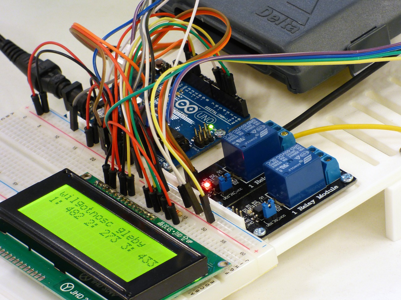
For the majority of electronic hardware products, a POC prototype will be built on an electronics development kit such as an Arduino or Raspberry Pi. Most electronic products require either a microcontroller or a microprocessor. The Arduino series of development kits are based on microcontrollers, and the Raspberry Pi and BeagleBone are based on microprocessors. A proof-of-concept prototype is usually only used to determine the practicality of a new product idea; it will rarely be seen by customers. Creating one makes the most sense if you have fundamental questions about whether your product can actually solve the intended problem.

Proof of concept prototype with breadboard, LED, relays, Arduino Uno, and wires
Figure 1: A POC prototype is built from off-the-shelf components and is commonly based on an Arduino or Raspberry Pi.

If there are multiple ways to solve a target problem, but you are unsure of which solution is best, then this prototype can provide a lot of valuable insight. Fundamental questions, such as the basic solution option, are much better determined by a POC prototype than with a custom PCB. If you are technically minded, you may be able to create your own prototype using an Arduino or Raspberry Pi. If you don’t have the skills to create your own POC prototype, and/or you have no major questions about the feasibility of your solution, it is probably better to skip the POC prototype altogether.

Most large tech companies bypass the POC stage, primarily because it’s a quicker path to market to start with a production version. Large companies also have a lot more money, so they can take expensive shortcuts that your average startup cannot afford.

Some design engineers also scoff at the concept of a POC prototype because they know they are rarely similar to the final production version. However, if you have fundamental questions or concerns about your solution, and you have a limited budget, then creating a POC prototype is time well spent. The downside is it increases the time it takes to get your product to market.

Looks-Like Prototype

A common strategy is to separate the appearance and feel of your product from the functionality. These are called looks-like prototypes and works-like prototypes.

A looks-like prototype focuses on optimizing the look, feel, form and aesthetics of the product. For this prototype you’ll use prototyping techniques such as foam, clay, 3D printing, CNC machining, and eventually injection molding.

When prototyping a new product you should separate the appearance of the product from the function of the product.

3D Printer printing an object
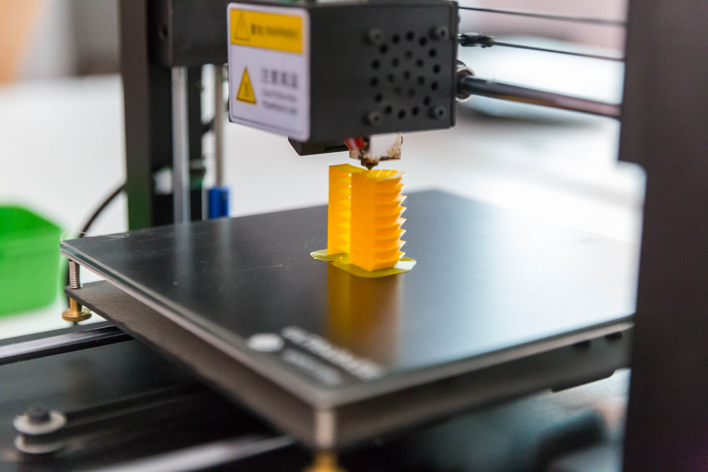
Figure 2: 3D printing is the most common method of producing looks-like prototypes, but CNC machining and even simple options like clay and foam should be not be neglected.

While they may seem overly simple, don’t neglect old techniques like foam and clay, which can be very helpful in the beginning stages. Both of these “technologies” allow you to quickly and cheaply transform a concept into something you can hold in your hand. Using foam or clay can be the cheapest and easiest way to experiment with the size, shape and feel of your product.

With my own electronics product, my earliest prototypes where made of clay. These clay models gave me critical feedback about how the product actually feels in a user’s hands. Starting with clay prototypes may also reduce the number of prototype iterations that you will need when you upgrade to 3D printing. Always start out with the simplest, cheapest methods of prototyping. Learn as much as you can from low cost prototypes before you migrate to more advanced prototyping technologies.

As you work your way up the prototyping technology hierarchy you will find that design changes become more and more complicated to implement. Clay prototypes are trivial to change, 3D printed prototypes are moderately complex/expensive to modify, and injection molded prototypes are the most complex to upgrade. So above all, keep things simple and learn as much as possible before upgrading prototypes.

  • 3D Printing: 3D printing is an additive prototyping process that adds material to create the desired shape. The term 3D printing is a broadly used term that actually refers to various prototyping technologies. Let’s look at the three types of 3D printers in more depth:

    1. Fused Deposition Modeling (FDM): This is the most affordable method of 3D printing and is therefore the most common technology used for home 3D printers. This technology can produce prototypes with a moderate amount of detail. FDM printers work by feeding plastic through a heated nozzle. The material is melted and deposited layer by layer, with each layer fusing to the layer below it. FDM printers are limited in the fine details they can produce so an SLA printer is a better option for complex prototypes.

    2. Stereolithography (SLA): SLA is a more costly process used mainly on high-end home 3D printers and by professional prototype shops. This type of 3D printer works by curing resin with light. The light hardens the liquid resin layer by layer in a process called photopolymerization. SLA is a very accurate method of 3D printing that can make parts with many fine details. SLA printers also produce a much stronger prototype because the layers are chemically bonded together. Prototypes produced by an SLA printer tend to look more professional than ones created with FDM printers. A good strategy for many entrepreneurs is to purchase a low-cost, FDM based 3D printer for producing early prototypes. Once the appearance and strength of the 3D printed prototype become more important you can move to using a professional prototype shop with SLA printers. This strategy will save you money and speed up development for many products.

    3. Selective Laser Sintering (SLS): An SLS system uses a laser to sinter (i.e. harden) powder materials layer by layer to form the desired shape. A big advantage of SLS is it can be used to create metal prototypes. Keep in mind that SLS is too complex for home 3D printers, so it’s only an option when using a professional prototype company.

  • CNC (Computer Numerical Control) Machining: The opposite of an additive process is a subtractive process. As the name implies a subtractive process removes material to form the desired shape. The process starts with a solid block of plastic or metal. Material is then carved away to form the final sculpted prototype. One of the primary advantages of CNC machining compared to 3D printing is that you have much more flexibility in regards to the material used. Not only can you create prototypes from plastic or metal, but you can select very specific plastic resins which precisely match the material you will use for mass production.

Works-Like Prototype

A works-like prototype is focused on the functionality of your product, which for most electronic products means the internal electronics. A POC prototype can be considered an early version of a works-like prototype, but now it is time to jump from a POC prototype to a production-level, works-like prototype. 
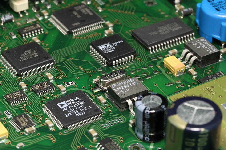
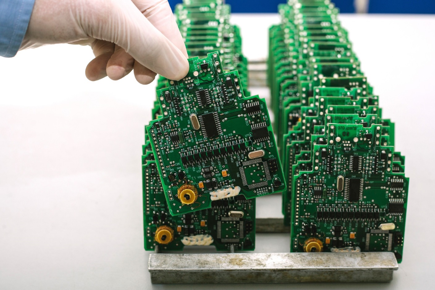
This means abandoning the use of development kits like Arduino. You now need to develop a custom Printed Circuit Board (PCB) to hold and connect all of your product’s discrete electronic components.

Example of a custom PCB with multiple components
Figure 3: There is a drastic jump in the technical skill to develop a custom PCB compared to the skill needed to make a POC using off-the-shelf components.

Developing a custom PCB for your works-like prototype requires significant engineering design experience. If you are fortunate enough to have these skills (SparkFun side note: or you want to leverage ALC!) then you will save thousands of dollars on development fees. Engineers are expensive and the development of this custom PCB is commonly the most expensive development cost you will face.

Prototyping the electronics:

How you begin prototyping your product’s electronics depends on what questions you are trying to answer. Every time you create a new prototype you should have well-defined questions that the prototype should answer. If you have broad questions about whether your product will even work, or whether it will solve the intended problem, then you should have already started with an early works-like prototype based on a development kit such as an Arduino or Raspberry Pi.

If there are no big questions about your product’s functionality then you should probably move right to designing a custom PCB. Most large companies developing products begin with a custom PCB. This is the fastest route to market, although not likely the cheapest. Prototyping a custom PCB consists of two steps: producing the bare PCB, and soldering on all of the components. We’ll discuss each process separately.

Although there are techniques for producing your own PCBs at home, they are limited to simple designs. So you will most likely need to outsource your PCB prototype production. Assuming you don’t make and assemble your own PCB boards, you’ll use the same process to produce your prototype boards, as well as to manufacture your boards in high volume.

The PCB production is summarized in the following steps:

  1. The process begins with a laminate core made from woven glass epoxy. It serves as an insulator between conducting layers and provides physical strength to the board.

  2. Single-sided boards consist of one laminate core with a copper layer on one side. Double-sided boards consist of a laminate core with copper layers on each side. Multiple layer boards consist of a stack-up of alternating copper layers with laminate core layers. Most boards will use two, four, six or perhaps eight conducting layers.

  3. The layout design for each conducting copper layer is laser plotted on film and a light sensitive chemical “resist” is applied. The copper layers are then exposed to high intensity ultraviolet light which shines through the film. This light hardens the resist layer over any copper traces and pads.

  4. The copper layers are then processed through a chemical solution which removes any of the resist layer that wasn’t hardened by the ultraviolet light. This leaves hardened resist material only over the desired copper traces and pads. Another chemical is then used to remove any exposed copper not covered by resist. The hardened resist layer is then removed, leaving only the desired copper to form the traces and pads.

  5. A lamination process is next used to bond all of the layers together to form the stacked PCB.

  6. Holes are drilled through the PCB stack-up to form vias which are used to connect signals on different layers. Any holes for through-hole components are also drilled. However, it’s generally best to only use surface-mount technology (SMT) components to minimize your soldering costs.

  7. Copper is next deposited on all exposed metal surfaces including the inner walls of any holes. Additional copper is electroplated onto all exposed copper surfaces.

  8. Now that the bare PCB is complete, the next step is to place and solder all of the electronic components. Robotic equipment called a pick-and-place machine uses a vacuum system to pick up the components and precisely place them on the PCB. Solder paste (a sticky mixture of solder and flux) is used to temporarily hold the parts in place.

  9. Finally, the boards are run through a reflow oven to melt the solder paste and form a permanent electrical connection between the component and the PCB pads.

Engineering Prototype

An engineering prototype (also sometimes called a works-like-looks-like prototype) is the first time that appearance and functionality come together in a single prototype. Once you have an engineering prototype you finally have something of sufficient quality to show customers and investors.

Example of an engineering prototype with many components such as wheels, chassis, lights, and other electronics
Figure 4 - An engineering prototype merges the works-like and looks-like designs together into a single prototype.

This is when it becomes a bit more practical to seek outside investors. By this stage, you’ve moved past most of the engineering and manufacturing risk. Investors obviously love this reduction in risk.

For my own hardware product I funded the product development myself up to this stage. I used my prototype to get a large, national retailer interested in my product. From there, I leveraged that success to find a manufacturer willing to fund the remaining prototype stages.

An engineering prototype is close to the production prototype, but it still hasn’t been tested or prepared for mass production.

Pre-Production Prototype

This is a works-like-looks-like prototype that has been optimized for manufacturing. This is very close to the final product your customers will see. In most cases, it should also include the retail package if the product will be sold via retail outlets.

Although the pre-production prototype may look and function very similar to the works-like-looks-like prototype, the key difference is manufacturability. During product development many entrepreneurs underestimate the work needed to migrate from a prototype to a product that can be efficiently manufactured. Making a few prototypes is completely different than manufacturing millions of units. In most cases, considerable additional design effort is required to prepare the design for mass manufacturing.

For example, 3D printing or CNC machining are typically used when prototyping the product’s enclosure. For mass manufacturing, high-pressure injection molding will be the technology used to produce the enclosure.

3D printing and CNC machining are very forgiving technologies and you can prototype just about any shape of plastic you can imagine. This is not the case with injection molding. Injection molding has very strict production requirements. After you finalize your 3D printed prototypes it will be necessary to further upgrade the design for injection molding.

  • Injection Molding: 3D printing is fantastic at producing tens of parts. However, it’s not practical for producing hundreds or thousands of parts. Ultimately, injection molding will be necessary to manufacture your product’s enclosure in higher quantities. Not surprisingly, the injection molding process starts with the creation of a mold. Molds are machined from metal, and the hardness of the metal determines the mold’s lifetime and cost.

For prototyping, or early production, aluminum molds are generally the best choice. Aluminum molds typically cost a couple thousand dollars each and can produce up to about 10,000 parts. The mold forms two halves that are held together as hot, molten plastic is injected at high-pressure into the mold. The high-pressure is necessary in order to produce fine details in the part. Once the plastic cools and solidifies, the mold is opened and the part is removed.

Most designs will require significant modifications in order to prepare them for injection molding. Be sure whoever designs your enclosure understands injection molding, otherwise you are likely to end up with a product that can be prototyped but not manufactured in high volume. Reaching the point of having a fully functional, works-like, looks-like prototype is a huge accomplishment, so pat yourself on the back once you achieve this milestone!

But don’t get too excited just yet... the transition from prototype to mass manufacturing is one of the most underestimated steps to bringing a new hardware product to market.

Engineering Validation Test (EVT)

Once you have a finished engineering prototype it’s time to begin testing it to validate that it works exactly as specified.

Two rows of green PCBs about to be tested
Figure 5 - The goal of the EVT stage is to prove that your product design meets the functional, performance, and reliability requirements.

The first stage of this testing is called Engineering Validation Testing (EVT). This stage of testing focuses on the electronics. Typically between 10-50 units will be tested during EVT. EVT will include testing the basic functionality but also doing various stress tests to ensure there are no hidden problems. This includes power, thermal and EMI testing. The goal of EVT is to validate that your prototype meets the functional, performance, and reliability specifications.

Design Validation Test (DVT)

The Design Validation Test (DVT) is one of the most complex stages. Its goal is to ensure the product meets any necessary cosmetic and environmental specifications. A significantly larger number of units will be needed than for the EVT stage, typically 50-200 units. These units will be very aggressively tested including drop, fire and waterproof testing. Validating that the product is durable enough to withstand day-to-day use is one of the primary goals of design validation testing. This is also commonly the stage at which electrical certifications are obtained. This includes certifications such as FCC, CE, UL and RoHS to name a few. Because of the cost and time required to obtain the necessary electrical certifications, the process is usually delayed until the DVT stage. This is to ensure that no other design changes are required after certification testing begins. Of course, if any problems are found during the certification testing process, then design modifications may be necessary to correct them.

Production Validation and Testing (PVT)

The PVT stage will be your first official production run. You will establish a pilot production line with the priority of optimizing your production process. The focus here will be on improving your scrap rate, assembly time, and quality control process by optimizing your production line, but not by making any further product design changes (unless a serious design issue is discovered). A small pilot production run of several hundred units is typical, and if no problems are found these can be your first units that can be sold!

Conclusion

One of the main things I hope you have learned from this article is that prototyping is a long process requiring many iterations. The prototype journey is complex and not to be underestimated. Don’t be in a rush to move up to more advanced prototyping technologies until you have gained all of the information you can from less complex, lower cost technologies. The idea that you simply create a single prototype (or two) and then just jump into full production should now be clearly seen as a myth.


This article was originally published at PredictableDesigns.com.

comments | comment feed

27 Nov 00:29

Cornhole Boards Play Victory Songs

by Kristina Panos
Jeremy

Where are yours, slacker

How do you instantly make any game better? By lighting it up and playing at night. We would normally say ‘drinking’, but we’re pretty sure that drinking is already a prerequisite for cornhole — that’s the game where you toss bean bags at holes in angled boards.

[Hardware Unknown] loves cornhole, and was gifted a set of portable, folding boards that light up around the ring for nighttime action. These turned out to be the perfect basis for reactive boards that light up and play sound whenever points are scored. Both boards have a vibration sensor to detect bags hitting the top, and an IR break-beam sensor pair across the hole. An Arduino Nano reads from the sensors and controls an amplifier and a DF Player for sound.

Players get a point and a song for landing a bag on top of the board, and three points and a different song for making it in the hole. We love the Easter egg — anyone who manages to trip both the vibration sensor and the break-beam detector at the same time will be treated to the sound of a flock of honking geese. Check out the build journey after the break.

No good at cornhole? This one doesn’t let you miss.

27 Aug 05:05

3D Printering: The World of Non-Free 3D Models Is Buyer Beware

by Donald Papp

There are more free 3D models online than one can shake a stick at, but what about paid models? Hosting models somewhere and putting a buy button in front of the download is certainly a solved problem, but after spending some time buying and printing a variety of non-free 3D models online, it’s clear that there are shortcomings in the current system.

What the problems are and how to address them depends a little on the different ways models get sold, but one thing is clear: poorly-designed 3D models are bad for consumers, and bad for the future of pay-to-download in general.

Different Ways Models Get Sold

There are quite a few different ways 3D models get sold online. Online sales are great for digital models because models are not physical goods, and serving a thousand buyers is no different from serving ten. A user technically pays for a license to use the model rather than purchasing it outright, and terms vary depending on the creators and providers.

Direct Sales (Pay per Model)

Direct sales work just like free 3D models, but with a price tag stuck in front of the download. Sites like Cults3D and MyMiniFactory allow creators to set prices on non-free models. Sales numbers are a bit hard to determine, but popular models have hundreds or a few thousand downloads.

A standout success is a site like Hero Forge, which allows users to create custom tabletop gaming miniatures with a web-based interface. Users can pay to download the STL of their creation, or pay for a printed version. Hero Forge is a proprietary system, but a highly successful one judging by their recent Kickstarter campaign.

Indirect Sales (Pay for Access to Models)

Indirect selling is when customers pay for access, rather than buying models individually. Successful creators make models in a niche area of interest, and people pay for ongoing access to the creator’s library of work.

Patreon is a common way for 3D model creators to manage monthly subscribers and provide access to files. Tabletop gaming is a common niche, and some of the bigger players have thousands of monthly subscribers.

Another way indirect sales are done is via crowdfunding campaign. Money is raised to create a specific set of models, and backers receive access to the resulting files. Again, tabletop gaming miniatures and terrain are over-represented in this area.

Kits Where Customers Print Their Own Parts

This approach sells 3D models as part of a product. Sold with or without additional hardware like electrical parts or fasteners, a purchaser buys a kit and prints their own plastic parts. As a result, the kit has fewer pieces, is easier to produce, cheaper to ship, and generally costs less than if the seller had to provide everything.

Examples of this business model include the (NERF-compatible) Bulwark Blaster, and the OpenScan (open-source 3D scanner.) In both cases, the project is built around 3D-printed parts and a solid bill of materials. Generally, the buyer is purchasing a single-use license for the printed parts.

Where Are The Problems?

In an ideal world, 3D printers reliably create any arbitrary shape without having issues with overhangs, bridges, distortions, or supports. One could purchase a 3D model and get exactly what’s expected. Sadly, we’re not there yet.

Good-quality 3D models must be designed specifically for 3D printing, and this is especially true if money is involved because in the current system, buyers accept all the risk.

No Test Drives, No Fitting Rooms, No Refunds

The world of non-free 3D models is a lot like a clothing store without a fitting room, or a showroom without test drives. “No refunds” is a common term of service and sale, and when combined with an inability to try before one buys, results can be unfortunate if a model is of poor quality.

Models With Poor DFM (Design for Manufacture) Exist

3D printers, like any tool, are good at some things, passable at others, and bad at the rest. That means models intended for 3D printing should be designed with the strengths and weaknesses of 3D printers in mind. A model that has been designed in such a way can be said to have good design for manufacture (DFM).

As designed, this model will require supports and post-processing no matter what orientation is chosen.

If a model has not been designed with 3D printing in mind, it can make life difficult for the person trying to print it. The trouble is that it’s not always possible to identify troublesome models by screenshots alone. Here are two examples.

The first is a simple latch from a larger assembly intended for FDM (filament-based) printing, shown here. The problem is subtle: the way it has been designed makes it virtually impossible to print reliably without needing supports, no matter the orientation. (It also had other problems, but more on that later.)

Adding supports means additional post-processing and a poor surface finish where the supports connect. If supports are placed on the latch’s presentation side, the part will be ugly. If supports go on a non-presentation side (where the hinge is) it invites fitment problems.

These issues can be solved with post-processing, but that’s not the point. The point is that it would be better to design the part in a way that avoids such problems in the first place.

Model sliced in two, with colors added for contrast between inner and outer layers. The model is not solid. Gaps where the outside layer (jacket) and inner layer (light blue) do not touch are a problem.

Another example is shown here. This model was advertised as being compatible with SLA (resin-based) printing. FDM and SLA printers are good at very different things, so it was encouraging to see a model specifically designed for SLA.

Unfortunately this turned out to not be the case. The model was not a solid figure. There are gaps between the outer layer (the figure’s jacket) and inner layer (the body) because they were modeled separately, and left as-is.

Not only do these gaps trap uncured resin, but the areas around the gaps are very thin, which invites print failures. In short, this model’s design choices ensure that the outside layers — the presentation surfaces — are the most likely to fail. These issues were not visible until after the model was paid for.

These problems and others like them demonstrate poor DFM that is not evident from screenshots and renders, and as mentioned earlier, pay-to-download is currently the land of No Refunds and Buyer Beware.

Why Bad Quality Models Are A Big Problem

The problem bad models cause is this: by the time a model has proven to be troublesome (or impossible, or wasteful) to print, a buyer has invested considerably more than the purchase price. All a bad model accomplishes is to alienate a person who was willing to mash a BUY button.

Having a buyer accept all the risk, only to have their expense of money and effort rendered worthless should be considered a worst-case scenario for any platform that is trying to grow.

Ways To Improve

It may be tempting to try to solve the issue of no returns or refunds with a system that can control access to downloaded files, but anything in this direction starts to look a lot like DRM, which is doubtful as a way forward.

It is possible to increase confidence about model quality and purchase without changing much about the underlying platforms as they currently exist. Here are some things that can be done.

Demonstrate Model Quality with Photos and Documentation

Documentation and photos (of the printed results, not just renders of the model) are an effective way to let a buyer know more about a model. Documentation doesn’t have to be long, but it should talk about design elements, assembly, or areas of special attention. An example is this model of a 3D printable vise by Christophe Laimer. It’s a free model, but excellent documentation in a way that builds confidence in the model’s quality.

Models that require additional hardware should have a clear bill of materials along with specifications and sources. That latch model I used as an example of poor DFM? It required a mystery spring of unspecified dimensions and no source; another issue not discovered until too late.

If a designer doesn’t clearly demonstrate that they have printed their own design successfully, don’t buy it.

Provide “Test Drive” Pieces

Designers of kits or other assemblies for sale can offer free access to small number of parts as a way of saying “if you can print these models and assemble them, you’re good to go because my product is designed using the same principles.” If customers cannot return purchases, this can at least provide a form of test drive.

Perform Automatic Quality Checks on Models

Professional print places like 3D Hubs perform an analysis of uploaded objects as part of their quote process, and warn about model features like thin walls, intricate details that could be lost, or the potential for hard-to-remove supports. Services responsible for hosting and selling models could increase buyer confidence by performing similar checks on models for sale, and showing the analysis along with the model and price.

What is Your Experience With Paid Models?

Have you bought models online, or do you sell your own designs? What’s been your experience, and what would you change about how it all works? Let us know your feelings in the comments.

26 Aug 02:49

Yes, Eufy Is Making a Smart Mailbox Now

by Gabe Carey on News, shared by Gabe Carey to Lifehacker
Jeremy

Not big enough, and you think a postal worker is going to sit around and wait for approval.

Eufy SmartDrop Mailbox | $199 | Kickstarter

Read more...

19 Aug 18:42

Our 12 Favorite Chrome Extensions

by David Murphy

The Chrome Web Store is a mess, sure, but that doesn’t mean that you shouldn’t use legitimate extensions to improve your browser experience—whether that’s on Google Chrome or the resource-friendlier alternative, Microsoft’s Edge Chromium.

Read more...

06 Dec 07:03

FreeCAD TechDraw Workbench Tutorial

by Al Williams

FreeCAD started out a little shaky, but it has gotten better and better. If you are trying to draw a schematic, it probably isn’t the best way to do it. However, it is a great graphical alternative to OpenSCAD for 3D printing and even incorporates OpenSCAD if you don’t want to choose. However, if you have a 3D part — regardless of how you want to create it in real life — having a proper mechanical drawing is very valuable. FreeCAD’s TechDraw workbench makes this very easy and [Joko] has a tutorial that shows exactly how to do it.

Machinists everywhere are used to looking at these drawings that typically show a top view, a front view, and a side view. The program will automatically project the views you select and then allows you to pick dimensions. It creates them and keeps them up to date if you change them in the model later.

The only things we had to remember from drafting class are which dimensions you need and which you don’t. FreeCAD just puts them where you tell it to.

If you need a mechanical drawing to show a colleague, a customer, a machine shop, or to file with a patent, FreeCAD has you covered. We didn’t try it, but you ought to be able to pull in OpenSCAD files and then create a drawing from that, as well.

FreeCAD is changing rapidly, especially if you download the latest versions. However, we did do a tutorial that will get you started. You can even send it data from KiCAD. Now if they would make a schematic workbench, we’d be very happy.

13 Oct 06:13

4 Thunderous Powered Car Subwoofers Under $300

by Russ Houberg

An SUV with a subwoofer in the open trunk, and speakers on the opened passenger's side door.
EugenePut/Shutterstock

If you’re looking to add a little more bass (no treble) to your car’s sound system, a good subwoofer is the way to do it. These combos can add some thunder without pounding your wallet.

What to Look for in a Powered Subwoofer System

Twenty years ago, if you wanted powerful bass for your car audio, you had to spend north of $1,000 to get a decent system. Thankfully, times have changed. You can get a great-sounding powered subwoofer package for less than $300! While you might not win any audio competitions with them, these inexpensive systems are an easy bolt-on to enhance the rumble of a factory car stereo or custom aftermarket sound system.

Here are some important factors to consider when you purchase a powered subwoofer for your vehicle:

  • Enclosure size and form factor: It’s easy to get an inexpensive, decent-sounding system. It’s not as easy to find one that sounds great and fits well in your vehicle.
  • Power: Subwoofer and amplifier power is best measured by Root Mean Squared (RMS) watts. RMS watts is the continuous power handling level into a given speaker resistance with a Total Harmonic Distortion (THD) of 1 percent or less. So, you’re looking for how much power the subwoofer/amp can handle continuously without sounding like garbage.
  • Frequency response: In most cases, larger woofers generate more volume and lower frequencies (deeper sound). But don’t get trapped by the bigger-is-better concept—that’s not always the case. There are some great 10-inch, eight-inch, and (surprisingly) six-inch subwoofers out there that generate a low, tight rumble.
  • Signal input options: Most powered subs support a line-level input from a subwoofer pre-output on a stereo head unit. But most factory stereos don’t provide subwoofer pre-outputs. Some subwoofers also support high-level inputs, which allow you to tap into the front or rear speaker wires directly to get the audio signal. The good news is this “tap” doesn’t actually have to drive the subwoofer; it just provides the sound stream to the subwoofer. It doesn’t affect the volume or quality of sound for the source speaker channel.

The key to adding good bass is to match the right size, power, and frequency response to the cabin volume of your vehicle. Larger interior spaces require more power, but also typically have more space for a larger system. A smaller interior often doesn’t require as much speaker size or power to achieve good bass. In a smaller car, you can get away with less power, and a smaller speaker size and installation footprint.

Best Overall: Rockville RWS12CA Slim 1200 Watt 12-inch Subwoofer

The Rockville RWS12CA subwoofer and remote.
Rockville

The Rockville RWS12CA combines a slim subwoofer box with a built-in monoblock amplifier and a 12-inch, shallow mount subwoofer. This system measures 24 inches (length) x 15 inches (height) x 4.37 inches (top depth) x 6.65 inches (bottom depth). It pushes 300 watts (RMS) and 1,200 watts (peak). The RWS12CA delivers powerful, cabin-filling bass in a form factor that’s easy to install, at a price point you won’t believe. The enclosure will fit under most rear crew-cab seats in a full-size truck. You could also easily stow it in the trunk of a car or the rear hauling space of an SUV.

The RWS12CA plays nice, with an aftermarket head unit that provides a line-level sound source and remote turn-on signal. You can also tap into high-level speaker lines to add it to a factory system. With an Auto Start Music Sense, the amplifier detects when the high-level speaker source provides a signal and turns on the amp power. A configurable low-pass crossover, +12 dB bass boost, and remote bass control are also included.

If you already have sub-wiring in place, you can knock $10 off the combo price. Otherwise, the Rockville RWS12CA + Wire Kit is the better value.

Best Overall

Rockville RWS12CA Slim 1200 Watt 12″ Powered Car Subwoofer Enclosure + Wire Kit

The quality of the Rockville RWS12CA’s deep, cabin-filling bass is matched by the configuration options of the amp. This, combined with the slim enclosure for installation flexibility, makes this our pick for Best Overall.

Best Bang for the Buck: MTX Terminator Dual 12-inch Powered Subwoofer

MTX Terminator subwoofer and TNA251 monoblock amplifier.
MTX Audio

Read the remaining 17 paragraphs

10 Jul 05:32

The Best Media Players for Windows and Mac

by Adam Pash and David Murphy

Everyone has something on their PC worth watching—that funny video you just shot on vacation, some movie you downloaded that you probably shouldn’t have, a highlight from your favorite concert, et cetera. And while you can probably just pull it up in your operating system’s default player, there’s no reason why you…

Read more...

21 Jun 02:58

Amazon upgrades the Fire TV Edition with Dolby Vision

by Cherlynn Low
At an intimate press event in the Dolby SoHo space today, Amazon announced a new Fire TV Edition with Dolby Vision. This is basically an upgraded Fire TV Edition, and the display model is made by Toshiba. A 55-inch model is available starting today f...
13 Jun 03:48

Samsung's next The Wall TV can stretch to 292 inches with 8K

by Jon Fingas
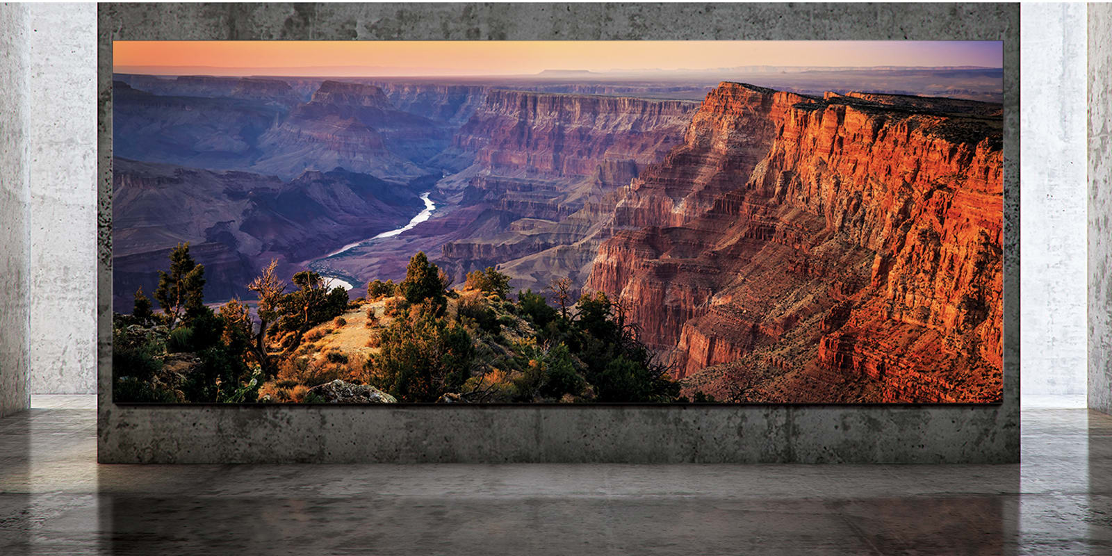
Samsung's 146-inch The Wall TV? That's for chumps. The electronics giant is fulfilling its promises of a home version by introducing The Wall Luxury, an even more ambitious TV designed for the poshest of abodes. It starts at 'just' 73 inches and 1...
07 Jun 03:49

The Best Way to Record a Remote Podcast Guest or Co-Host

by Levi Sharpe

You know what’s annoying? Tuning in to a podcast that advertises a really great guest, only to find that the whole 30-minute interview with that guest is a phone recording.

Read more...

01 Jun 13:48

Paul Allen's Stratolaunch is reportedly shutting down

by Mariella Moon
Paul Allen's space company, Stratolaunch Systems Corporation, is reportedly closing down its operations. According to Reuters, the company is shutting up shop, but it's also exploring the possibility of selling its assets and intellectual property. A...
01 Jun 13:44

Gigabyte's next-gen SSD shows the incredible potential of PCIe 4.0

by Steve Dent
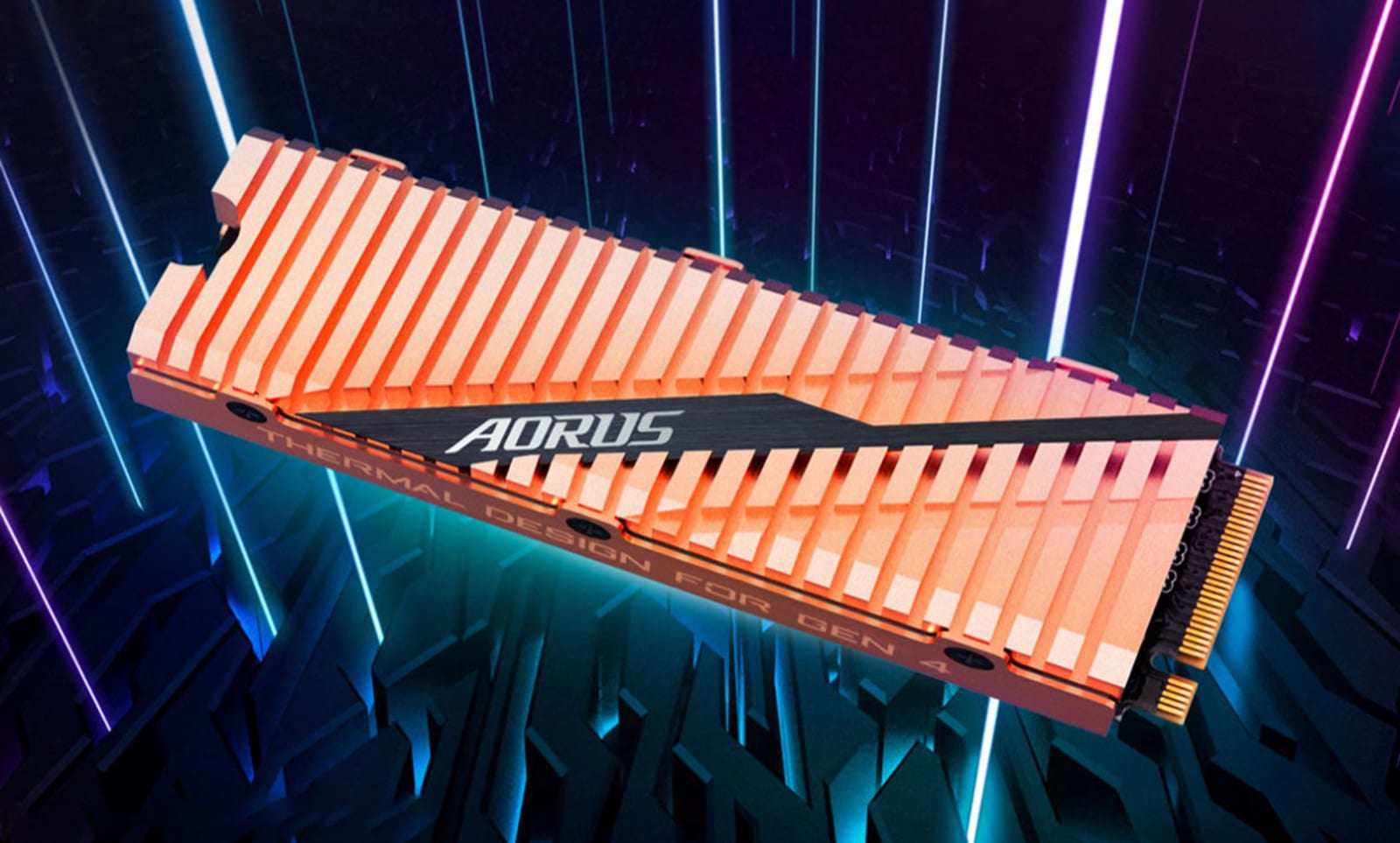
When AMD launched its third-gen Zen 2-based Ryzen processors, it also introduced the next generation PCIe 4.0 controllers. Now, Gigabyte has launched one of the first PCIe 4.0 NVMe SSDs that shows the incredible speed potential of the new tech. The A...
26 May 04:26

Is it Actually Bad to Have 100 Browser Tabs Open?

by Andrew Heinzman
Jeremy

I'm usually a 20 tab guy.

A pair of hands working on an extremely messy desk.
KREUS/Shutterstock

Through all of human history, a mess of tabs has been a sign of poor productivity. But that 100-tab habit could be the secret to your productivity, so long as you have the right extensions and hardware.

The Case for 100 Tabs

When it comes to productivity, everyone has different needs. Some people like to write to-do lists, some people like to stand while they work, and others like to keep 100 tabs (or more!) open at a time. If you’re the kind of person that loves a mess of tabs, then congratulations, society despises you for the one thing that makes you unique.

At some point in the last 20 years, civilized society decided that a mess of browser tabs is like a stack of dirty dishes or a hoarder’s front porch. Today, tab-junkies are treated like savages, as if they were never disciplined as children for opening too many tabs.

But, in reality, a mess of tabs can be a sign of productivity. There are situations where you need to have 100 tabs open, especially if you’re researching a dense subject or juggling a handful of projects.

Sadly, society’s misconceptions have made it difficult for tab-junkies to optimize their special form of productivity. Google (among other browsers) refuses to improve its tabbing system, so if you want your tabs to feel more like an organized bookshelf and less like Einstein’s messy desk, then you have to hunt down extensions and learn annoying tab-cleaning habits.

Not to mention, modern browsers require a ton of system resources, and webpages can demand more than 2 GB of RAM. Even the most productive tab-junkies will run into lag, stuttering, and crashes while running 100 tabs on an underpowered PC.

So, if you’re a tab lover, then it’s time to take things into your own hands. You can easily optimize your 100-tab productivity by using browser extensions, and you can make the most of your PC (even if it’s a crappy PC) by upgrading a few pieces of hardware.

Or, if those tabs get in your way and slow down your computer, there are some good ways to close tabs and save them for later.

RELATED: How to Not Have 100 Browser Tabs Open

It’s Time to Wrangle Those Tabs

Read the remaining 17 paragraphs

26 May 04:20

Surprising cause of infant deaths: Car seats used for naps when not in car

by Reuters
Jeremy

Guess we should ban these too, just like the rockers. Blame the manufacturer instead of incompetent parents.

26 May 04:16

Why Disney+ Freaks Me Out About the Future of Streaming

by Alex Cranz

It certainly seems like the world of streaming video entered a new epoch recently. Last week, Comcast finally handed the reigns of Hulu over to Disney, which means the company will have not only the impending Disney+ streaming service but also a live TV service that competes with the big cable companies. Then, the…

Read more...