Back in December, I posted that we’re building an open laptop. The post generated hundreds of comments, and I was surprised there was so much interest.
To be honest, that was overwhelming. Also, there were many who didn’t get what we’re trying to do — as indicated by suggestions along the vein of “use a Core i7 and a fast nVidia graphics chip and sell it for under a hundred bucks and then I’d buy it”.
Rather than try to convince the Internet about my opinions, or suffer the distraction of running a Kickstarter campaign around a very complex and risky project, I decided to hunker down and stick with what I do best — hacking hardware.
Despite the lack of updates here, the project is alive and kicking. All our progress has been publicly trackable via our git repos and on our wiki. There’s also a discussion forum, although I tend to check in only once every month. The board-bringup process and feature validation matrix is noted here, and the list of changes from EVT to DVT is documented here. We also had a little adventure writing code that could calibrate wire delays on the DDR3 bus for a variety of SO-DIMM modules.
The TL;DR version of the wiki documentation is: the board has gone through a major revision, and received a few upgrades that I think really refines its vision.
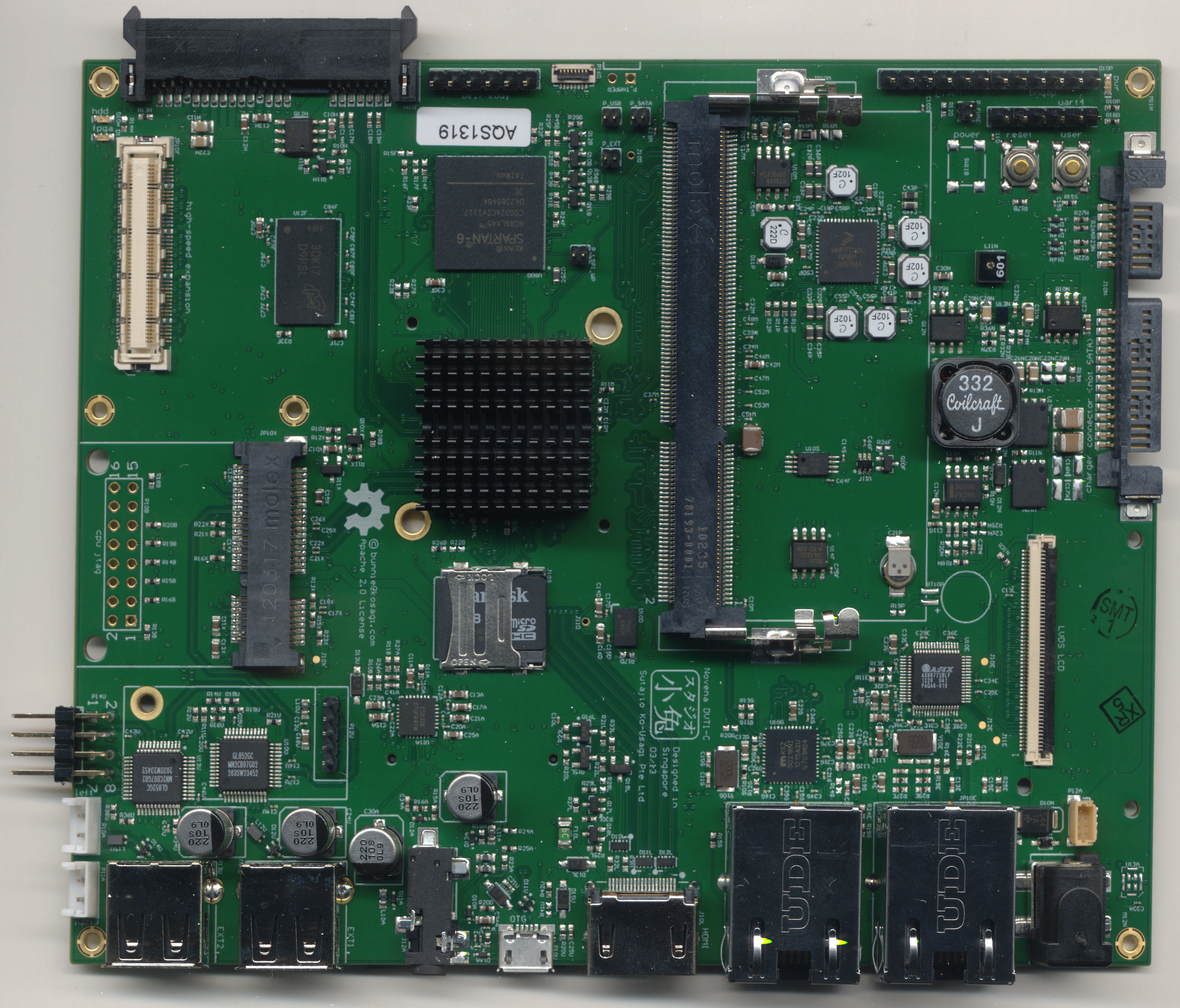
The FPGA
For me, the integration of the FPGA is a real point of differentiation, so I beefed it up; the DVT version sports a bigger Spartan 6 LX45 FPGA and an upgraded power supply to feed it. I want to be able to use the FPGA to do more coprocessing and data acquisition, and so I added a 2 Gbit DDR3 buffer, connected via a 16-bit, 800MT/s bus. And finally, I want to be able to plug in various high-speed data acquisition modules, so I dropped the Raspberry Pi header and low-speed analog I/Os, replacing the entire cluster with a single high-speed expansion header. The new high speed header breaks out 21 differential pairs plus some single-ended pins. This is sufficient to mate dual 8-bit 500++ Msps ADCs onto the FPGA, making for a fairly decent signal acquisition system.

The Display
I really care about having a lot of pixels on my laptop. So we revised the LCD interface to be easily upgradeable and interchangeable using mezzanine adapter boards. The first adapter board we designed is for a Retina display. We’re now using an LG LP129QE: 12.85″, 2560 x 1700 pixels (239ppi), with a 24-bit color depth. It looks gorgeous.

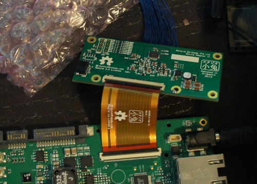
Below is what the mezzanine board looks like. Dual 24-bit LVDS channels, power, PWM, I2C and USB are fed into the mezzanine via a custom flex cable. The board itself has an LVDS-to-displayport converter chip, and connects to the display via the new IPEX-style micro-coaxial connectors.
I’ve spent some time on the ID, but I’m not ready to share those details with the world yet; however, I will say that the case will use leather and aluminum, and it’s designed to be open, accessible, and easily upgradable to future versions of the motherboard.
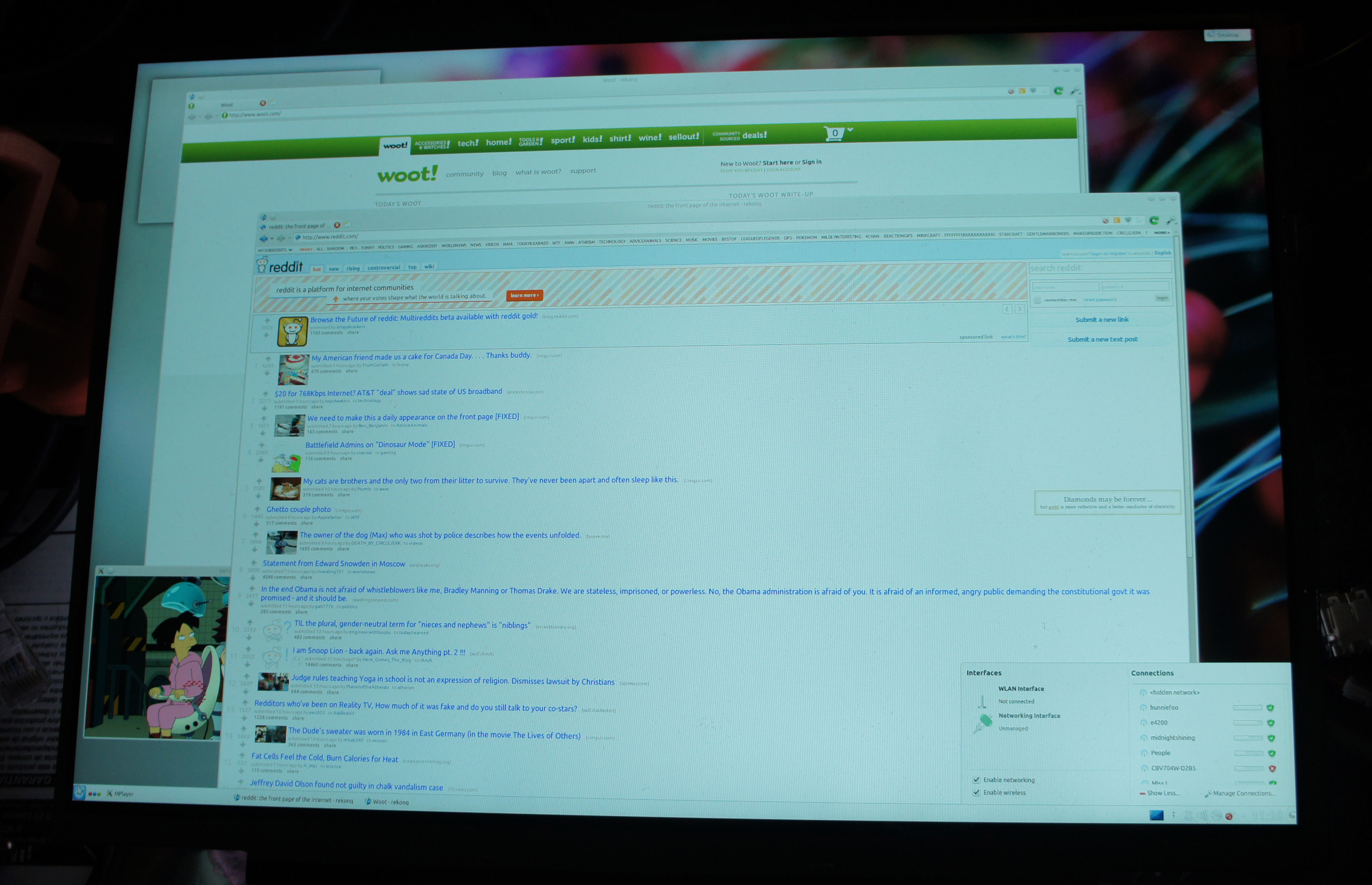
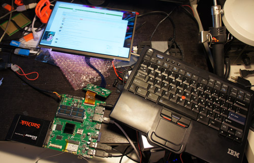
In the meantime, we’ve been developing on the system in an “exploded” fashion. The system below shows all the essential elements together and working; keyboard/mouse, LCD, hard drive, mainboard, hosting its own development environment. The desktop environment shown below is stock armhf Ubuntu with our custom kernel, but that is far from a final decision; we’re testing a broad field of distros for compatibility and convenience.
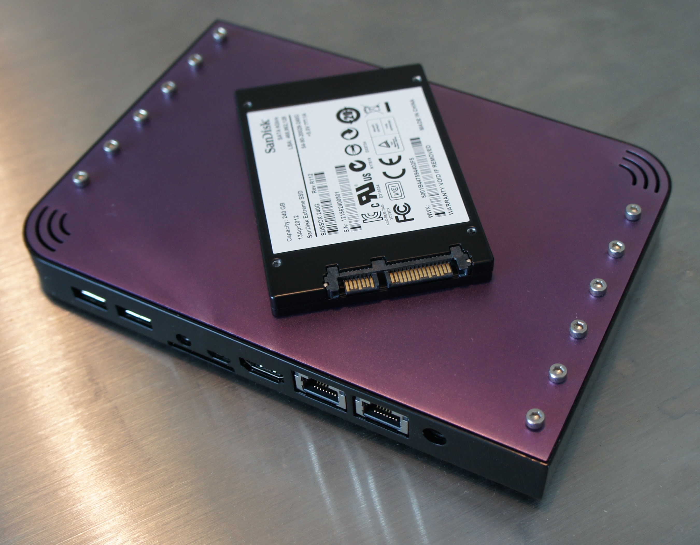
The Router Case
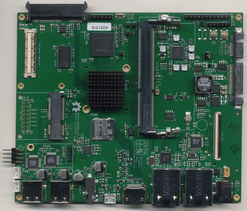
We’ve had a lot of interest from people wanting to use the Novena system as a secure router — the openness of the system is a selling point to many in that space. To that end, we’ve made a conversion case that can house the mainboard alone in a design suggestive of a conventional router.
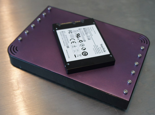
The 2.5″ hard drive is shown for size scaling.
The lid is anodized aluminum, and most of the screws on the top are decorative. I wanted to buck the design trend of mysterious black monoliths and playing hide-the-screws. Instead, the screws are featured front-and-center, inviting the user to twist them and open things up. “There is no magic in this box. Open me and you shall understand.”
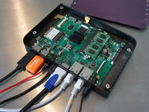
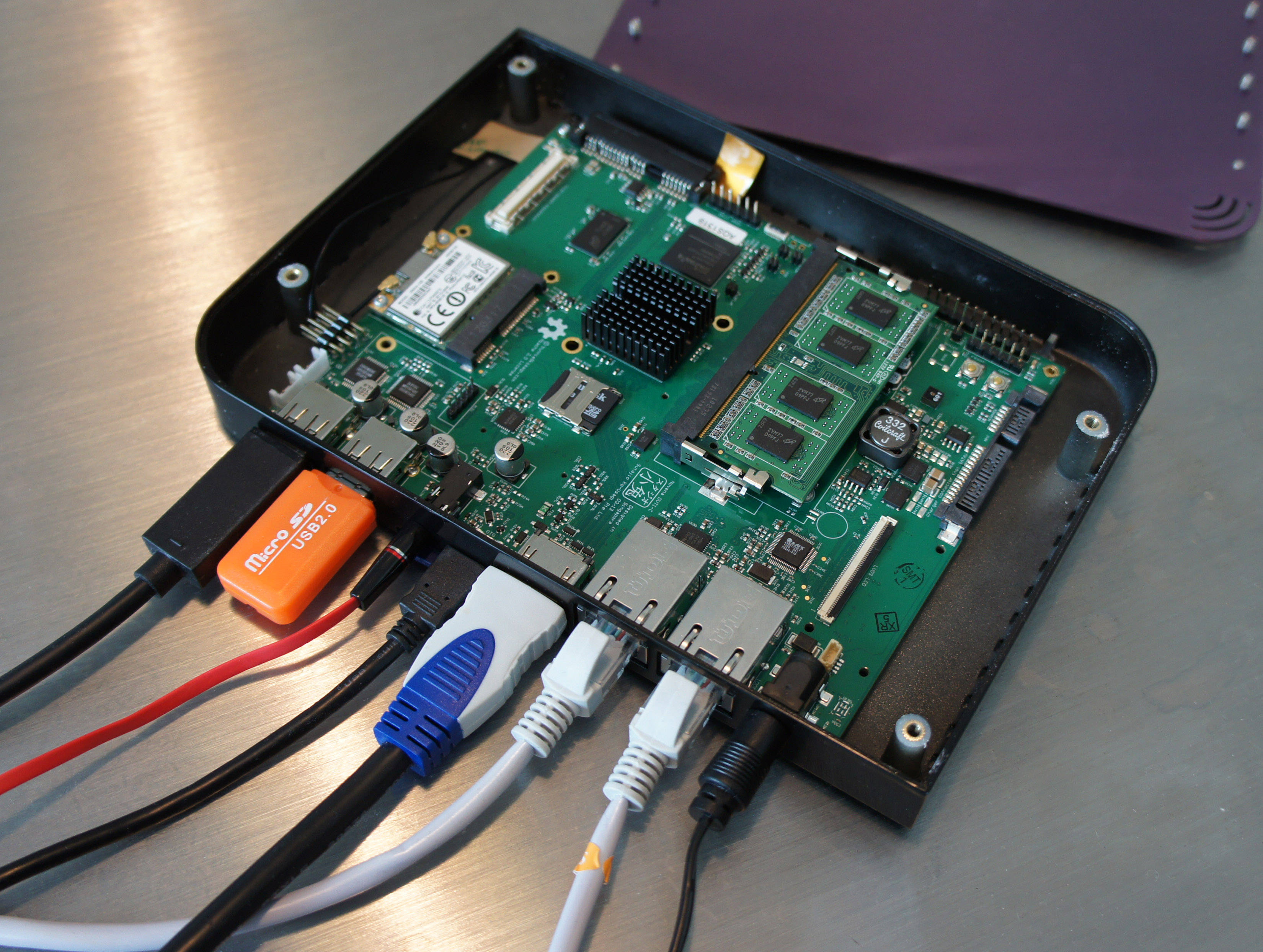
Above is the “router” with the lid off and all the ports filled. Probably for the partners I’m working with, we’ll depopulate all of the ports except for the dual ethernet, OTG, and the power jack to reduce cost.
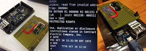
The First Hack (Romulator)
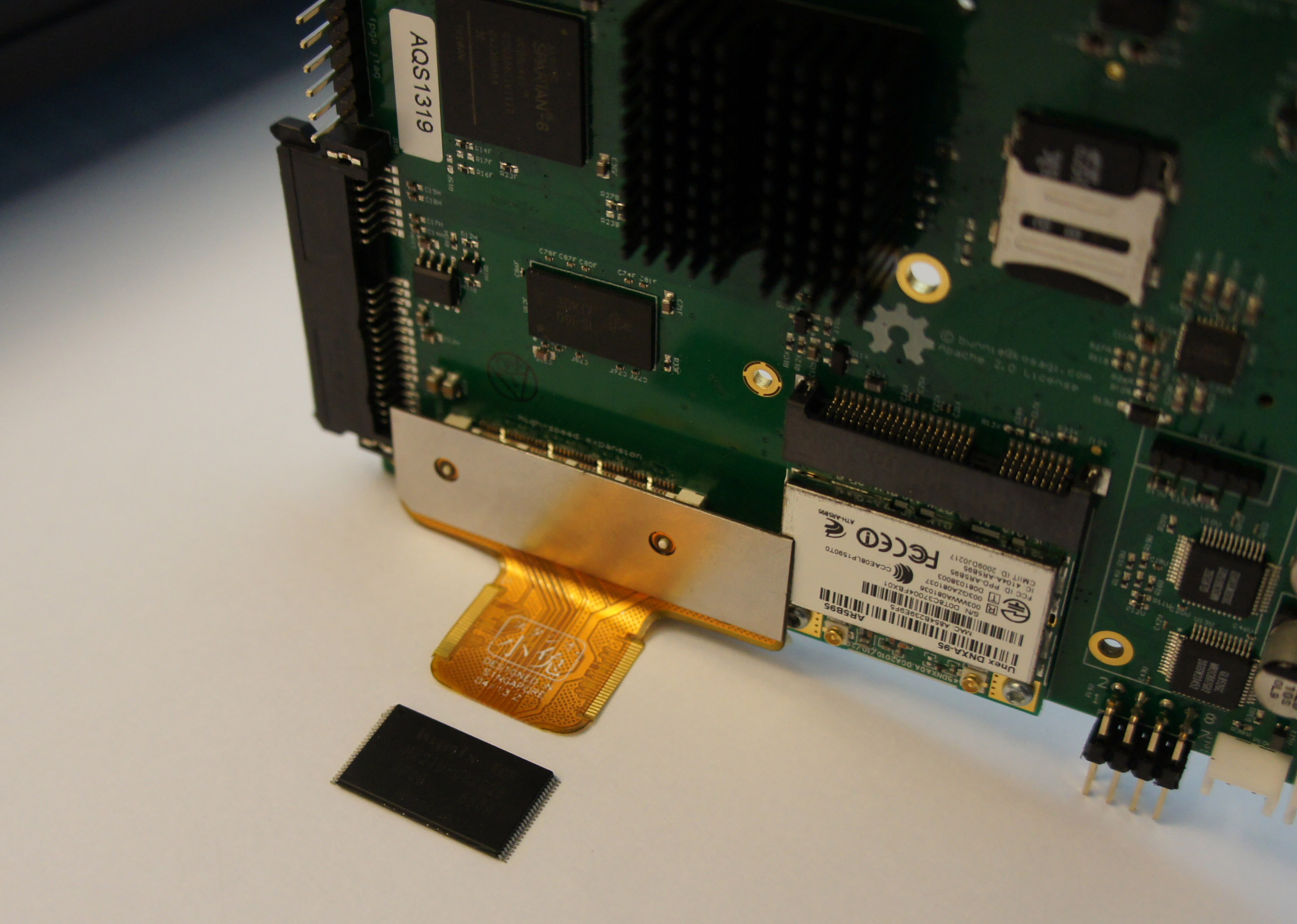
Already the DVT version of Novena has been put to task in helping with our hacking projects. We implemented a “romulator” using the high speed interface, FPGA and DDR3 combo.

The idea is to do real-time, in-circuit emulation of NAND FLASH using the FPGA + DDR3. The FPGA faithfully emulates a NAND device, whose contents can be monitored and modified real-time by the i.MX6 CPU — the DDR3 interface has oodles of bandwidth, and the interface macro provided by Xilinx is configured to provide four virtual access ports to the RAM. In addition, 16MB of the DDR3 is reserved for a logic analyzer-style trace capture of the NAND traffic, so we can dig through the time history of complex transactions and figure out what happened and what went wrong.
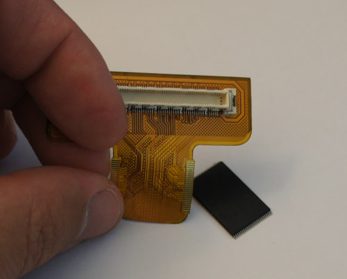
A small flexible circuit board adapter plugs into the high speed expansion socket. The board is thin enough to be soldered underneath a FLASH chip for passive monitoring, or directly to the target motherboard for active emulation.
Other boards will be made that plug into the high speed port. My short list includes a high speed ADC board, variants focusing on digital signal acquisition, and PHYs to standards such as USB or HDMI.
The Bottom Line
At the end of the day, we’re having fun building the laptop we always wanted — it’s now somewhere between a python-scriptable oscilloscope, logic analyzer, and a laptop. I think it will be an indispensable tool for hacking, particularly for doing signal analysis which requires coordination across multiple protocol layers, complex trigger conditions and/or feedback stimulus loops.
As for the inevitable question about if these will be sold, and for how much…once we’re done building the system (and, “done” is a moving target — really, the whole idea is this is continuously under development and improving) I’ll make it available to qualified buyers. Because it’s open-source and a bit quirky, I’m shy on the idea of just selling it to anyone who comes along wanting a laptop. I’m worried about buyers who don’t understand that “open” also means a bit of DIY hacking to get things working, and that things are continuously under development. This could either lead to a lot of returns, or spending the next four years mired in basic customer support instead of doing development; neither option appeals to me. So, I’m thinking that the order inquiry form will be a python or javascript program that has to be correctly modified and submitted via github; or maybe I’ll just sell the kit of components, as this would target buyers who know what they are getting into, and can RTFM. And probably, it will be priced in accordance with what you’d expect to pay for a bespoke digital oscilloscope meant to take a position at the lab bench for years, and not a generic craptop that you’ll replace within a year. Think “heirloom laptop”.
Anyways, that’s the update. Back to hacking!