Shared posts

02 May 14:30

Debunking the Drone Versus Plane Hysteria

by Jenny List

The mass media are funny in the way they deal with new technology. First it’s all “Wow, that’s Cool!”, then it’s “Ooh, that’s scary”, and finally it’s “BURN THE WITCH!”. Then a year or so later it’s part of normal life and they treat it as such. We’ve seen the same pattern repeated time and time again over the years.

The mass media tech story cycle. Our apologies to Gartner. Curve image: Jeremykemp [ CC BY-SA 3.0 ], via Wikimedia Commons
Seasoned readers may remember silly stories in the papers claiming that the Soviets could somehow use the technology in Western 8-bit home computers for nefarious purposes, since then a myriad breathless exclusives have predicted a youth meltdown which never materialised as the inevitable result of computer gaming, and more recently groundless panics have erupted over 3D printing of gun parts. There might be a British flavour to the examples in this piece because that’s where it is being written, but it’s a universal phenomenon wherever in the world technologically clueless journalists are required to fill column inches on technical stories.

The latest piece of technology to feel the heat in this way is the multirotor. Popularly referred to as the drone, you will probably be most familiar with them as model-sized aircraft usually with four rotors. We have been fed a continuous stream of stories involving tales of near-misses between commercial aircraft and drones, and there is a subtext in the air that Something Must Be Done.

The catalyst for this piece is the recent story of a collision with a British Airways plane 1700ft over West London approaching London Heathrow. The ever-hyperbolic Daily Mail sets the tabloid tone for the story as a drone strike, while the BBC’s coverage is more measured and holds a handy list of links to near-miss reports from other recent incidents. This incident is notable in particular because a Government minister announced that it is now believed to have been caused by a plastic bag, and since there is already appropriate legislation there was little need for more. A rare piece of sense on a drone story from a politician. The multirotor community is awash with plastic bag jokes but this important twist did not seem to receive the same level of media attention as the original collision.

Are multirotors unfairly being given bad press? It certainly seems that way as the common thread among all the stories is a complete and utter lack of proof. But before we rush to their defence it’s worth taking a look at the recent stories and examining their credibility. After all if there really are a set of irresponsible owners flying into commercial aircraft then they should rightly be bought to book and it would do us no favours to defend them. So let’s examine each of those incident reports from that BBC story.

At this point, not being multirotor experts we did what every sane writer should when faced with that situation but few do. We sought someone with the expert knowledge to shed some light on the matter. A friend of Hackaday is a multirotor flier and builder of many years experience, and as we continue it is his input that informs the writing here.

Analyzing Incident Reports

So, that out of the way, on to the incident reports. These are proximity reports from the UK Airbrox Board, the body whose task is to apply any of the lessons that can be gleaned from any such incidents to air safety. They are all downloadable in PDF format.

Hyde, Greater Manchester. The incident should be somewhere towards the hills in the background. Smabs Sputzer (CC BY 2.0) vial Flickr.
Hyde, Greater Manchester. The incident location should be somewhere towards the hills in the background. Smabs Sputzer (CC BY 2.0) via Flickr.

Our first is Airprox Report No. 2015141. A Dornier 328 was above Hyde approaching Manchester Airport on the afternoon of 27th August 2015, at 2800 feet above sea level (about 1500 feet above local ground level) with a speed of 180 knots (207.141 mph). The drone was seen by the pilot, and was a royal blue trirotor, about 50cm in diameter.

As the report notes, this drone would certainly have been breaking the law by flying over the legal 400 feet, and the operator would almost certainly have been using an FPV camera. But let’s return to the report, at 50cm this is not a big machine. If it was a drone, its chances of carrying enough battery power to take it to 2800 feet while also both carrying and powering an FPV camera and transmitter could not be very high at all. Even at ground level these machines don’t have very long flight times, and climbing to that altitude is a power-hungry task. Remember that multirotors have propellers designed for efficiency in the thick air of ground level, and as they climb they have to work ever harder.

There is also the question of it being reported as a trirotor. This is not an unknown multirotor configuration, but such a machine is highly unusual in the UK. Unusual enough for anyone operating one to be noticed, we think.

12 o'clock to 1 o'clock on a reciprocal track. Petr Adam Dohnálek [CC0] (Wikimedia)/Andreas 06 [PD] (Wikimedia)
12 o’clock to 1 o’clock on a reciprocal track. Petr Adam Dohnálek [CC0] (Wikimedia)/Andreas 06 [PD] (Wikimedia)
Moving on, we have Airprox Report No. 2015155, a Boeing 737 departing Stansted Airport at 4000 feet and 250 knots (287.696mph) in the late afternoon of the 13th of September 2015. The aircraft reported as a drone had a fuselage 2m in length, the air crew could not say whether it was jet or propeller powered. It was reported as going from the 12 o’clock position to the 1 o’clock position in a reciprocal track.

Reading this report, we find it difficult to understand how it could responsibly be attributed to a multirotor by any of the media outlets. This describes an aircraft capable of making an extremely tight turn (refer to this page about clock positions in aviation to appreciate this if our diagram isn’t enough) over an airliner traveling at nearly 300mph at 4000 feet (Stansted is a lot closer to sea level than the terrain surrounding Manchester). We’re not fast jet specialists here at Hackaday, but wouldn’t that kind of turn be impressive performance even for a military fighter? Disregarding all the stuff from our discussion of the previous report about the difficulty of a battery powered multirotor achieving that altitude, even in their wildest dreams a multirotor owner can’t make their machine perform like that!

The UK Houses of Parliament. Mike Gimelfarb [Public domain], Wikimedia
Our credulity now stretched, we move on to Airprox Reprt No. 2015157, an Embraer E170 approaching London City Airport at 2000 feet and 160 knots (184.125 mph) around midday on the 13th of September 2015. The aircrew reported “a silver drone with a ‘balloon-like’ centre and 4 small rotors on each corner”, and air traffic control confirmed the pilot had reported the incident while over the Houses of Parliament.

A balloon-like drone would be an unusual machine, but while it may be out of the ordinary it is not an unknown configuration. The Festo machine we have just linked to for example was so unusual as to have received worldwide coverage when it was announced. But like the previous reports the problem we find with this report is the altitude. The power required to get a machine to 2000 feet and stay there without running out of juice and plummeting to earth would push the abilities of multirotor battery technology to the limit. If you notice in the Festo demonstration, it is all performed indoors, without weather or significant altitude.

The real kicker here though is the location. Over the UK Houses of Parliament. If you wanted to run an experiment in how quickly you could get a free ride in a British police car, we’d suggest you try flying an unexpected multirotor in this airspace. It is some of the most tightly-monitored space in the country, full of twitchy security people fueled by The War Against Terror, and one of very few places in the UK where you’ll see police officers carrying guns. Couldn’t it just be that the pilot in fact saw an escaped novelty helium balloon, not entirely impossible over one of the most populated parts of the country?

Datchet from the air. se71 (CC BY-NC-SA 2.0) via Flickr.

Next on the list is Airprox Report No. 2015162, a Boeing 777 over Datchet climbing out of London Heathrow at 2000 feet and with a speed not reported. We’d expect the aircraft to be under acceleration at this point, so it is likely that it would be moving at a similar speed to the earlier Stansted incident.

The 777 pilot described a quadcopter, about 12 to 18 inches in diameter, and with motors the size of Coke cans on each corner. The encounter was fleeting, only a very few seconds as the 777 was in a steep climb.

There are plenty of off-the-shelf quadcopters that are about 12 to 18 inches in diameter. Container loads of them arrive from China every day, and they would have delighted a million children when unwrapped on Christmas morning. But a couple of things bother us about this report. First there is the weight and power issue we’ve mentioned when discussing the previous reports. A machine that size would not be capable in our view of reaching 2000 feet under control with an FPV camera and staying there for any appreciable time and then returning under its own power. Batteries simply are not available which are light enough to both hold that amount of power and to enable them to do this. Our second concern though comes from those motors. There are large motors for multirotors, it is true. They have higher power output and correspondingly larger electrical power demands, and you might see them on much larger machines driving larger rotors. But would it make sense to fit them to such a small airframe? We just can’t see it. Our friendly expert’s comment on this report was that it sounded as though someone who had seen a picture of a multirotor but had never handled one was trying to describe what they thought one was.

Our next incident is Airprox Report No. 2015172, an Airbus 319 over Poyle on final approach to London Heathrow at 500 feet and 140 knots (161.110 mph) on the morning of the 30th of September 2015. The pilot reported a small drone-like helicopter hovering close to the centre line. He estimated that it passed within 20 to 30 feet of his aircraft.

Unlike the previous reports, this one does not stretch the possibilities of what a multirotor or model helicopter could achieve. A toy drone or helicopter might struggle, but there are enough more capable machines available. It is not at an altitude difficult to reach with a battery-powered aircraft, nor is it beyond the possibility of controlling such an aircraft from the ground. It also finds the Airbus at its point of most vulnerability, when as an aircraft approaching the runway it lacks both the airspeed and airspace to evade another craft or to recover itself in the event of an incident.

There is however one anomaly about this incident which we feel bears further investigation. A multirotor is a small and lightweight machine, and if it were to pass within 20 feet of an airliner at low altitude traveling at 160mph it is likely that it would experience significant turbulence. In simple terms, it would be knocked out of control by the wash of the passing high speed airliner, and there is a significant likelihood that it would not have been able to remain in the air. It is certain that an investigation would have immediately begun to find any wreckage of a crashed drone, yet none was found.

Gatwick airport from the air. Phillip Capper (CC BY 2.0) via Flickr

Our final case is Airprox Report No. 2015212, An Airbus A321 in the final stages of approach to Gatwick Airport in the early afternoon of the 28th of November 2015. The co-pilot reported seeing a stationary drone hovering at about 100 feet over the touchdown zone. The airliner passed underneath it and the co-pilot lost sight of the drone when he was at about 20 feet above ground level.

As with the previous report, this does not push the boundaries of multirotor flight. All but the most ineffectual drones should be capable of hovering at 100 feet above ground level, indeed since it is below the UK 400 foot altitude limit they could do so perfectly legally away from somewhere like Gatwick.

There is however a troubling side to the story that we would like to see an explanation for. Unlike all the other reports, this incident took place within the confines of an active and busy international airport. Airports are crawling with people doing a multitude of jobs, and yet nobody else saw the drone. The incident happened at 13:45 and the police were on the scene at 13:52, an astoundingly quick response for UK police, yet there was no drone. If you take a look at the Gatwick touchdown zone on Google Maps, you will see it is hardly close to the perimeter of the airport, to make a successful escape in that time the drone would have had to fly rather quickly, have an excessive amount of battery power, and somehow be invisible to everyone in the area surrounding the airport. We come back to our theoretical experiment in how quickly a drone pilot could get a free ride in a British police car, we strongly suspect the reality would be that any real drone pilot doing so at Gatwick would find themselves eating porridge in a very short time indeed. If this turns out not to be the case, shouldn’t questions be being raised about the airport’s security?

We Need Better Reports

It is very important to stress that flying a multirotor or any other kind of aircraft in proximity to a commercial airliner is a crime. It’s a particularly dangerous crime, and one which can have disastrous consequences in the event of a collision. We’d go further, and suggest that if anyone is found to have been doing it they should be locked up. Throw away the key, no collecting $200 or passing Go, all the clichés. It’s a crime, and any perpetrators should face all the consequences with maximum prejudice.

We are however concerned by the tone of all the reports listed above, both as they appear in the media and as they are reported in the official incident documentation. It is reported as indisputable fact that they are all multirotors being flown illegally, yet the only evidence presented are somewhat dubious eyewitness reports, either of extremely fleeting views of the craft in question or of craft that very obviously can not be electric hobby multirotors. At no point has anyone produced a real multirotor as evidence, in fact the only incident that featured a collision was found to be with a plastic bag. We feel that reporting these incidents in this way is irresponsible, and not consistent with the high standards we would expect from an aeronautical investigative body.

Unidentified objects in the air have been a feature of aviation since the first fliers took to the skies. They have been variously explained at different times as birds, weather balloons, secret Nazi weapons, Russian spies, or even alien invaders, but the common thread when you come down to it is that nobody has a clue what they really are. It seems that the current Flavour Of The Month when you have a sighting is to blame it on a drone, but that default identification seems about as meaningful in this context as it was when people were blaming aliens.

It was reassuring to hear the UK Government response that no new legislation was required, at least those of our community in the UK whose interests lie in multirotors will be spared hasty legislation driven by tabloid newspaper outrage like the disastrously ill-conceived Dangerous Dogs Act. But as we mentioned at the start of this piece, though we’ve used UK examples to illustrate here, this is not an issue confined to one country. If we want to keep our ability to fly it’s important that we expose any bogus truths behind drone panic stories wherever we find them, help bring to book any pilots we find breaking the rules we have at the moment, and continue to fly with care and consideration for other users of the airspace.


Filed under: Current Events, drone hacks, Featured, news, Original Art, slider
02 May 07:13

Has Mankind Gone Too Far With Drone Fishing?

by Gerrit Coetzee

Previously man was limited in his ability to fish the waters of this world by the power of his arm or his ability to procure the services of a boat. Now, as long as man is willing to risk a thousand dollar drone set-up, he can descend upon unsuspecting fish with robotic precision. It is very unfair, and awesome.

The concept is simple. Buy one of those drones every upper middle class teenager seems to get for Christmas. Attach a streaming camera set-up to it. Next, rig it up so that it can fly the fishing line from the rod out, but when the fish bites the line can easily detach. Finally, attach a friend to the controls of the fishing rod.

After that it’s like shooting fish in an ocean. Fly the drone around, pulling the line behind you, until you see a school of fish. Next, dangle the bait in the center of the school. Inevitably one will strike, the line will detach, and it’s up to your friend to reel in your catch. Either that or a bunch of tuna will wreck your drone and you’ll get to watch a livestream of a thousand dollars sink to the ocean floor. Video after the break.


Filed under: drone hacks
22 Apr 15:02

Hacking When it Counts: POW Canteen Radios

by Dan Maloney

Of all the horrors visited upon a warrior, being captured by the enemy might count as the worst. With death in combat, the suffering is over, but with internment in a POW camp, untold agonies may await. Tales of torture, starvation, enslavement and indoctrination attend the history of every nation’s prison camps to some degree, even in the recent past with the supposedly civilizing influence of the Hague and Geneva Conventions.

But even the most humanely treated POWs universally suffer from one thing: lack of information. To not know how the war is progressing in your absence is a form of torture in itself, and POWs do whatever they can to get information. Starting in World War II, imprisoned soldiers and sailors familiar with the new field of electronics began using whatever materials they could scrounge and the abundance of time available to them to hack together solutions to the fundamental question, “How goes the war?” This is the story of the life-saving radios some POWs managed to hack together under seemingly impossible conditions.

No Atheists in a Foxhole

Many POW radios are extensions of foxhole radios, a common pastime of soldiers in WWII. A resourceful soldier living in the field could likely have scrounged or looted a complete radio, or at least could have rounded up the parts to make a decent regenerative receiver for news and entertainment in the field. But the local oscillator of even such a modest receiver could be detected by the enemy, so crystal radios were preferred. With nothing but a tuned circuit and rectifier cobbled from a safety-pin and a razor blade, crystal foxhole radios were undetectable and could be used to tune in commercial broadcasts and military transmissions.

A replica foxhole crystal set. Photo: Bill Jackson
A replica foxhole crystal set. Photo credit: J.G. Jackson

Foxhole radios would be easy to replicate in the POW camps, and to some degree might operate better than they would in the field. POWs often used the long runs of barbed wire in the camp fences as antennas, and the waste produced by the camp led to ample opportunity to scrounge parts.

With that in mind, many of the POW hackers looked for ways to improve their foxhole radios. The most obvious improvement was adding a capacitor to the coil to create a proper LC circuit, rather than depending on the stray capacitance of the antenna. Scoring a variable capacitor to tune the radio was an even bigger coup.

Life or Death Hacking

A step up from the foxhole-style crystal set was a simple regenerative receiver. The richer scrounging and greater likelihood of finding mains or battery power in the POW camp led to these receivers, grouped under the general heading of canteen radios from one common way of concealing them.

One especially well-documented build was that of an American amateur radio operator named Captain Russell Hutchison. He built a fairly complex single tube regenerative receiver into a standard GI canteen while interned by the Japanese in the Cabanutuan concentration camp in the Philippines.

N6CC's working replica of Hutchison's canteen radio. Source. CanteenSWRadio

Hutchison had the relative good fortune to be tapped as the fix-it guy for the camp; even the Japanese relied on him to repair their gear. Radios looted by Japanese soldiers made it to Hutchison for repair, and pilfered parts began to accumulate. Eventually Capt. Hutchison had enough parts to build his radio, which was sensitive enough to copy shortwave transmissions from as far away as San Francisco using a covert antenna of fine wire woven into a clothesline.

Hutchison’s radio was a matter of life and death in more than one way. The most pressing concern was being discovered with the set, which would result in summary execution. To avoid that fate, Hutchison took elaborate measures beyond the canteen subterfuge to ensure that as few men in the camp as possible knew about his hack.

Despite several near-misses, the radio was never discovered and Hutchison eventually made it out of the camp alive. But the radio served another life and death role. Far from being just an amusement to pass idle hours, the radio was used to monitor the progress of the expected invasion of Japan. The POWs realistically feared their captors would execute them and destroy the evidence of their atrocities as soon as Allied boots hit the Japanese Home Islands; the radio kept the POWs one step ahead so that they could try to escape before the bullets started flying.

Something from Nothing

As impressive as Hutchison’s hack was, at least he had manufactured components to work with. There were other POW hackers that weren’t so fortunate, but still needed the connection to the outside world that radio provided. With the same mortal stakes at play, these hackers built radios from almost nothing. Take the case of one Lt. Colonel R.G. Wells, a British officer interned in a Japanese concentration camp in Borneo. In 1942, he created almost every component of a superheterodyne receiver from found objects. Capacitors were made from the foil lining of a tea chest and the few precious scraps of newspaper that weren’t horded for alternate duty in the latrines. Resistors were pieces of string impregnated with burnt cinnamon bark. Bare wire was insulated by rubbing flour nicked from the mess into palm oil and caking it onto the wire. A chromic acid wet cell was concocted of potassium dichromate “donated” by the camp pharmacy and zinc trouser fly buttons. When that proved insufficient to power the radio, Wells built a chemical cell that both rectified the camp’s AC supply and dropped the voltage to a usable level.

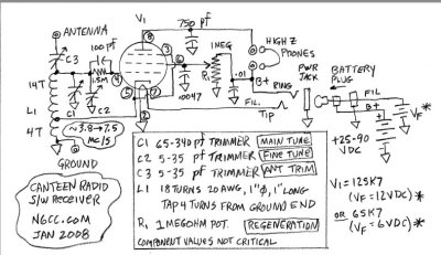
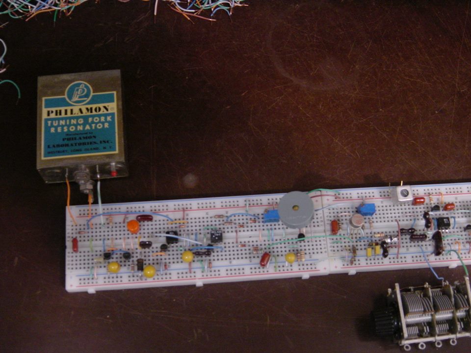
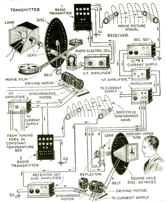
The only components Wells couldn’t conjure out of thin air were the vacuum tube and the headset. Wells’ detailed oral history of the radio doesn’t say much about where the tube came from, but it does record that the headset was smuggled into the camp. Given enough time, the resourceful Col. Wells no doubt could have manufactured a headset; indeed, a Vietnam POW named Richard Lucas built the headset for his foxhole radio using a core of nails wrapped with wax-insulated wire in a bamboo resonator with a tin can lid for a diaphragm. He reported that it worked well enough to hear several stations, but that the headset would have worked better with a magnet to bias the coil.

As impressive as these hacks are, more amazing still is the fact that all of it was done from memory. These POWs came into camp with nothing but their dog tags and the clothes on their backs, and sometimes not even the latter. There were no reference books or cheat sheets. The circuits these men built under impossible conditions, often with only the rawest materials, were committed to memory, probably from days and nights of experiments in the pre-war years. Their hobby paid off in a big way and allowed them to hack their way through a more difficult time than any of us can likely imagine.


Filed under: classic hacks, Featured, radio hacks
20 Apr 15:34

Casting A Lathe Out Of Concrete

by Brian Benchoff

Look up ‘concrete lathe’ and you’ll quickly find yourself reading the works of [David Gingery]. His series of books on building a machine shop from scrap begin with a charcoal foundry, and quickly move to creating a metal lathe out of concrete. Before [Gingery]’s lathe, around the time of World War I, many factories created gigantic machine tools out of concrete. It’s an old idea, but you’ll be hard pressed to find anyone with a shop featuring concrete machine tools. Cheap lathes are plentiful on Craigslist, after all.

Building a metal lathe from concrete is more of a challenge. This challenge was recently taken up by [Curt Filipowski] in a five part YouTube series that resulted in a real, working lathe made out of concrete, scrap, and a lot of bolts.

The concrete lathe begins with a form, and for this [Curt] cut out all the parts on a CNC router. Creating the form isn’t quite as simple as you would think – the concrete form included several bolts that would alow [Curt] to bolt bearings, ways made out of gas pipe, and angle iron. This form was filled with concrete in [Curt]’s kitchen, and after a nice long cure, the lathe was moved up to the upstairs shop. That’s a five hundred pound block moved up a flight of stairs by a single person.

The rest of the build deals with the cast concrete carriage which rides along the polished gas pipe ways, a tool post holder milled out of a block of aluminum, and finally making some chips. While it’s not the most practical lathe – the carriage moves along the ways by turning a wheel underneath the tailstock – it does demonstrate a concrete lathe is possible.


Filed under: tool hacks
18 Apr 14:26

‘Wow!’ Signal Was…Wait For It…Comets

by Bob King

The Wow! signal recorded on August 15, 1977. The ones, twos and threes indicate weak background noise. Letters, especially those closer to the end of the alphabet, represent stronger signals. The “6EQUJ5” is read from top to bottom (see graph below) and shows the signal rising from “6” to “U” before dropping back down to “5”. Credit: Big Ear Radio Observatory and North American AstroPhysical Observatory (NAAPO)

Comets get blamed for everything. Pestilence in medieval Europe? Comets! Mass extinctions? Comets! Even the anomalous brightness variations in the Kepler star KIC 8462852 was blamed for a time on comets. Now it looks like the most famous maybe-ET signal ever sifted from the sky, the so-called "Wow!" signal, may also be traced to comets.Say it ain't so!In August 1977, radio astronomer Jerry Ehman was looking through observation data from the Ohio State's now-defunct Big Ear radio telescope gathered a few days earlier on August 15. He was searching for signals that stood apart from the background noise that might be broadcast by an alien civilization. Since hydrogen is the most common element in the universe and emits energy at the specific frequency of 1420 megahertz (just above the TV and cellphone bands), aliens might adopt it as the "lingua franca" of the cosmos. Scientists here on Earth concentrated radio searches at and around that frequency looking for strong signals that mimicked hydrogen.Ehman's searches turned up mostly background noise, but that mid-August night he spotted a surprise — a vertical column with the alphanumerical sequence “6EQUJ5" that indicated a strong signal at hydrogen's frequency. Exactly as predicted. Big Ear picked up the signal from near the 5th magnitude star Chi-1 Sagittarii in eastern Sagittarius not far from the globular cluster M55.Astonished by the find, Ehman pulled out a red pen, circled the sequence and wrote a big "Wow!" in the margin. Ever since, it's been called the Wow! signal and considered one of the few signals from space that defies explanation. Before we look at how that may change, let's make sense of the code.Each digit on the chart corresponded to a signal intensity from 0 to 35. Anything over "9" was represented by a letter from A to Z. It was probably the "U" that knocked Ehman's socks off, since it indicated to a radio burst 30 times greater than the background noise of space.In Big Ear's 35 years of operation, it was the most intense, unexplainable signal ever recorded. What's more, it was narrowly focused and very close to hydrogen's special frequency.Big Ear listened for just 72 seconds before Earth's rotation carried the signal's location out of "view" of antenna.  Since the radio array had two feed horns, the transmission was expected to appear three minutes apart in each of the horns, but only a single one ever picked it up.Despite follow-up observations by Ehman and others (more than 100 studies were made of the region) the signal was gone. Never heard from again. Nor has anything else like it ever been recorded anywhere else in the sky.Careful scrutiny eliminated earthbound possibilities such as aircraft or satellites. Nor would anyone have been transmitting at 1420 MHz since it was within a protected part of the radio spectrum used by astronomers and off-limits to regular broadcasters. The nature of the signal implied a point source somewhere beyond the Earth. But where?If it really was an attempt at alien contact, why try only once and for so short a time interval? Even Ehman doubted (and still doubts) an extraterrestrial intelligence origin, but a much more recent suggestion made by Prof. Antonio Paris of St. Petersburg College, Florida may offer an answer. Paris earlier worked as an analyst for the U.S. Department of Defense and returned to the "scene of the crime" looking for any likely suspects. After studying astronomical databases, he discovered that two faint comets,  266P/Christensen and 335P/Gibbs, discovered only within the past decade, had been plying the very area of the Wow! signal on August 15, 1977.If you recall, a comet has two or three basic parts: a fuzzy head or coma and one or two tails streaming off behind. Invisible to earthbound telescopes, but showing clearly in orbiting telescopes able to peer into ultraviolet light, the coma is further wrapped in a huge cloud of neutral hydrogen gas.As the Sun warms a comet's surface, water ice or H2O vaporizes from its nucleus. Energetic solar UV light breaks down those water molecules into H2 and O. The H2 forms a huge, distended halo that can expand to many times the size of the Sun.Paris published a paper earlier this year exploring the possibility that the hydrogen envelopes of either or both comets were responsible for the strong 1420 MHz signal snagged by Big Ear. On the surface, this makes sense, but not all astronomers agree. First off, if comets are so radio-bright in hydrogen light, why don't radio telescopes pick them up more often? They don't. Second, some astronomers doubt that the signals from these comets would have been strong enough to be picked up by the array.A quick check on 266P and 335P at the time of the signal show them both around 5 a.u. from the sun (Jupiter's distance) and extremely faint at magnitudes 22 and 27 respectively. Were they even active enough at those distances to form clouds big enough for the antenna to detect?Paris knows there's only one way to find out. Comet 266P/Christensen will swing through the same area again on Jan. 25, 2017, while 335P/Gibbs follows suit on January 7, 2018. Unable to use an existing radio telescope (they're all booked up!), he's begun a gofundme campaign to purchase and install a 3-meter radio telescope to track and analyze the spectra of these two comets. The goal is $20,000 and Paris is already well on his way there.It would be a little bit sad if the Wow! signal turned out to be a "just a comet", but the possibility of solving a 39-year-old mystery would ultimately be more satisfying, don't you think?

The post ‘Wow!’ Signal Was…Wait For It…Comets appeared first on Universe Today.

18 Apr 14:23

Teslaphoresis: Tesla Coil Causes Self-Assembly In Carbon Nanotubes

by Moritz Walter

teslaphoresis_strings_1

This significant discovery in nanotechnology could also be the first practical use of a Tesla coil in modern times that goes beyond fun and education. A self-funded research team at Rice University has found that unordered heaps of carbon nanotubes will self-assemble into conductive wires when exposed to the electric field of a strong Tesla coil. The related paper by lead author and graduate student [Lindsey R. Bornhoeft], introduces the phenomenon as “Teslaphoresis”.

teslaphoresis_leds_1
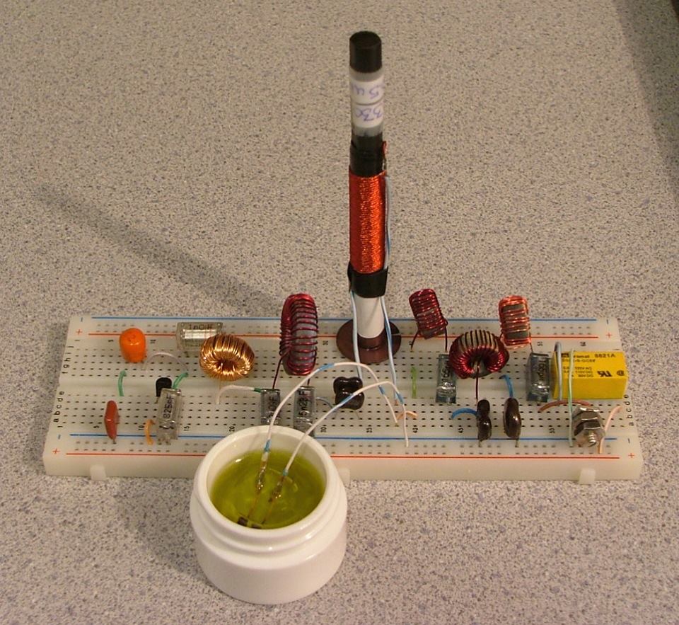
“I would have never thought, as a 14-year-old kid building coils, that it was going to be useful someday” says Rice University chemist [Paul Cherukuri], who redesigned the classic Tesla coil to produce a stronger, more directed force field and built the research prototype. The team also found that their idea of self-assembly could be extended to little LED circuits, which apparently harvest energy from the coil’s field to light up the LEDs.


Rendering of a single walled carbon nanotube – by Arnero

Carbon nanotubes are microscopic tube-like structures from carbon atoms. Because of their special mechanical and electrical properties, researchers are currently searching for practical applications thereof. In particular, carbon nanotubes can be semiconductors, metals and superconductors depending on their structure, but a scalable method of assembling them into practical circuits has yet to be found.

Further studies will have to prove or disprove how and to what extent the described self-assembly process can actually be controlled or is applicable, but the recent demonstration certainly gives you a taste of the potential of the discovery. We are curious to hear if any of our readers had ever tried something similar on their own coils – let us know in the comments!

Thanks to [Mechanicus] for the tip!


Filed under: hardware
10 Apr 05:47

Screw Drive Tractor Hasn’t Conquered Canada Yet

by Gerrit Coetzee
Daniel Isaza

@davidpelaez

[REDNIC79] lives somewhere in Canada where key terrain features include mud and snow. Half pontoon boat, half auger, screw-propelled vehicles excel in this kind of terrain as long as you’re okay with going really slow.

In his 11-and-counting part video series, [REDNIC79] goes through the conversion of a lawn tractor into a slow, theoretically unstoppable, Canadian screw-propelled tractor. He welds a frame, plonks some beefy chains on it, and throws a few hefty looking bearing mounts on there to boot. Then he makes some screws out of gas tanks; which was an enormous amount of work.

It was time to fire up the tractor. On the first muddy incline encountered, the tractor ceased to move. The culprit? A cracked transmission housing. Ouch. The end of the shaft holding the chain for the right screw was unsupported. When the shaft turned, it imparted its rotational force, but there was also an unconsidered down force on the end of the shaft, which resulted in a moment the bell housing wasn’t designed for.

Undeterred, [REDNIC79] welded the housing back together and threw a bearing on the end of the offending shaft to balance the moments. He fired it up, engaged the transmission, and the right screw bearing pillow block completely shattered. Ouch again. We can safely begin to assume that screw-propelled vehicles see a lot of forces.

[REDNIC79] hasn’t shelved the project yet. His next plan is to beef up the supports and build a much larger set of screws with smaller blades out of some propane tanks. This should reduce the force the power house needs to put out. Video of the first fail after the break.


Filed under: misc hacks
10 Apr 05:32

Hacking Flappy Bird By Playing Mario

by Elliot Williams

This is a hacking and gaming tour de force! [Seth Bling] executed a code injection hack in Super Mario World (SMW) that not only glitches the game, but re-programs it to play a stripped-down version of “Flappy Bird”. And he did this not with a set of JTAG probes, but by using the game’s own controller.

There are apparently a bunch of people working on hacking Super Mario World from within the game, and a number of these hacks use modified controllers to carry out the sequence of codes. The craziest thing about our hack here is that [Seth] did this entirely by hand. The complete notes are available here, but we’ll summarize the procedure for you. Or you can go watch the video below. It’s really incredible.

First, there’s a “powerup incrementation glitch” that lets you get Mario into an undefined powerup state. Then [Seth] executed another hack to stop the game’s timer, so that he would have plenty of time to play around.

2016-03-30-123215_1366x1792_scrotFrom here, he could enter bytes directly into RAM by positioning Mario in exactly the right place and dropping a mushroom. Mario’s x-coordinate value was written to memory. [Seth] had to get Mario on exactly the right pixel just by comparing his position against the background. That’s so incredibly tedious and requires such precision that the first few bytes of code he entered were a routine that displayed Mario’s position in the coin counter. You can see this working around 3:30.

The next trick is to add in a bootloader that lets him enter bytes by spin-jumping. This lets him enter bytes relatively easily — move to the right position indicated in the coin display, and then spin-jump. By this point, the graphics are all messed up, but he’s live-patching a running system at the byte level, so what do you expect? The coolest feature of the bootloader? A checksum at the end verifies the code so that you can pick up again at the code entry phase, rather than having to re-do a half hour’s worth of “up-up-down-down-left-right-left-right-B-A”.

In the end, a rudimentary “Flappy Bird” game is loaded into the system. It only took [Seth] an hour to pull this off, but the early parts of the chain are so critical that he can’t make any mistakes. The next time you’re sitting around with your disassembler/debugger and type backspace, imagine having to restart over again from the beginning. This is high-wire hacking without a net. Amazing!

Thanks [gudenau] and [Le Samourai] for the tip!


Filed under: nintendo hacks
27 Mar 21:00

Photos: Soyuz Rocket blasts off from Russia to deliver Military Mapping Satellite

by Patrick Blau

A Soyuz 2-1A rocket lifted off from the Plesetsk Cosmodrome on Thursday, successfully lifting the Bars-M No.2 mapping satellite to orbit in a nine-minute ascent mission taking the spacecraft to the expected Sun Synchronous Orbit.

>>Read our Launch Recap

All Photos: Russian Ministry of Defence

12512651_1723671317875617_91265244290882670_n 72376_1723671641208918_4435265201530328366_n 12512373_1723671644542251_1878175863320101150_n 12495078_1723671724542243_8910071367258698252_n 12804873_1723671621208920_392533323373114700_n 12494915_1723671314542284_2474104408962155116_n 12472372_1723671367875612_993492637957603494_n
27 Mar 20:15

Solar Storms Ignite Aurora On Jupiter

by Evan Gough

Composite images from the Chandra X-Ray Observatory and the Hubble Space Telescope show the hyper-energetic x-ray auroras at Jupiter. The image on the left is of the auroras when the coronal mass ejection reached Jupiter, the image on the right is when the auroras subsided. The auroras were triggered by a coronal mass ejection from the Sun that reached the planet in 2011. Image: X-ray: NASA/CXC/UCL/W.Dunn et al, Optical: NASA/STScI

The Earthly Northern Lights are beautiful and astounding, but when it comes to planetary light shows, what happened at Jupiter in 2011 might take the cake. In 2011, a coronal mass ejection (CME) struck Jupiter, producing x-ray auroras 8 times brighter than normal, and hundreds of times more energetic than Earth's auroras. A paper in the March 22nd, 2016 issue of the Journal of Geophysical Research gave the details.The Sun emits a ceaseless stream of energetic particles called the solar wind. Sometimes, the Sun ramps up its output, and what is called a coronal mass ejection occurs. A coronal mass ejection is a massive burst of matter and electromagnetic radiation. Though they're slow compared to other phenomena arising from the Sun, such as solar flares, CMEs are extremely powerful.When the CME in 2011 reached Jupiter, NASA's Chandra X-Ray Observatory was watching, the first time that Jupiter's X-ray auroras were monitored at the same time that a CME arrived. Along with some very interesting images of the event, the team behind the study learned other things. The CME that struck Jupiter actually compressed that planet's magnetosphere. It forced the boundary between the solar wind and Jupiter's magnetic field in towards the planet by more than 1.6 million kilometers (1 million miles.)The scientists behind this study used the data from this event to not only pinpoint the source of the x-rays, but also to identify areas for follow-up investigation. They'll be using not only Chandra, but also the European Space Agency's XMM Newton observatory to collect data on Jupiter's magnetic field, magnetosphere, and aurora.NASA's Juno spacecraft will reach Jupiter this summer. One of its primary missions is to map Jupiter's magnetic fields, and to study the magnetosphere and auroras. Juno's results will be fascinating to anyone interested in Jupiter's auroras.Here at Universe Today we've written about Jupiter's aurora's here, coronal mass ejections here, and the Juno mission here.

The post Solar Storms Ignite Aurora On Jupiter appeared first on Universe Today.

23 Mar 09:51

Photos: Soyuz thunders off in the Dark of Night

by Patrick Blau

Russia’s Soyuz rocket made a nighttime liftoff on Friday to deliver the Soyuz TMA-20M spacecraft with Alexey Ovchinin, Oleg Skripochka and Jeff Williams to orbit, setting out on a fast-track rendezvous with the International Space Station.

>>Read our Launch Recap

All Photos: NASA/Aubrey Gemignani

25894027305_3ad3b83300_ky 25773268552_5d9f3f85fe_k 25773263962_221ff46a91_k 25894027305_3ad3b83300_k 25799146521_1d84ae8864_k 25894037705_dd25cc660a_k 25773318722_dc40915726_k 25773279952_bcd08b8a4b_k 25593538840_a2beee792e_k
17 Mar 23:54

Carrington Probabilities

by Steve McDonald

K7RA's 'Solar Update' in this week's ARRL News, mentions Jeff Foust's recent article in 'The Space Review', reminding us again of the dangers posed by a modern-day 'Carrington Event', also known as the 'Solar Storm of 1859'. A large solar flare in late August, hurled a monster-sized CME towards earth, making the 93 million mile journey in just 17.6 hours compared with the more normal rate of several days.

Huge auroras soon lit up the sky as far as central Mexico, Hawaii and the Caribbean. The aurora was so bright, it was reported that Rocky Mountain goldminers awoke in the middle of the night, and thinking morning had arrived, started to prepare breakfast. Telegraph lines and equipment burst into flame while some circuits continued to be usable with power supplies completely disconnected. The 1859 event still remains the most geoeffective solar storm since records have been kept.

Such an event today, of course, would wreak much more havoc ... probably having devastating consequences for decades and causing trillions of dollars of damage.

From Foust's article:

Was that, though, just a fluke event? .... Pete Riley, senior research scientist at Predictive Science Inc., offered a probabilistic forecast for the likelihood of another Carrington-like event, based on that storm’s estimated strength and measurements of the actual strength of solar storms over the last few decades. “If you the (sic) time between events, you can calculate the probability of the next event occurring within some unit of time,” he explained. 

His estimate of the probability of another Carrington event is surprisingly high: about a 10 percent chance of such an event occurring over the next decade. “Ten percent is very, very high,” said William Murtaugh, assistant director for space weather at the White House’s Office of Science and Technology Policy (OSTP) ... “A one-percent probability over the course of the next one hundred years of a storm with an impact of that magnitude is considered very, very high and will motivate action.”

Interestingly, for this prediction, the actual strength of the solar storm of 1859 can only be estimated. If it was actually twice as strong as thought, then the probabilities drop from a (decade) 10% probability to just a 1% chance.

The U.S. government has recently set up a NASA multi-million budget funding proposal to study the likely effects of future large scale impacts and possible “response and resiliency capabilities” but it's not known if these will carry over to any new administration.

“Fortunately in space weather there’s no real politics,” Murtaugh said. “Both sides of House, both sides of the Senate, Republicans and Democrats, are both keen to work together to do something about this issue.”

The article has brought some interesting 'food for thought' comments, among them:

I think it is excellent that there are steps being taken to improve our understanding of the probabilities and predictive accuracy of such solar events, but I'm concerned that it isn't entirely clear how that information will translate into major investments in civil engineering that will make us less vulnerable to them. As for asteroidal impact threats, it's one thing to have a observations and research that will provide predictive information, and another to prevent tragedy. In both cases, it's about how we'll actually prevent such destructive effects once predicted. Prevention is a LOT more expensive than prediction, and is thereby ripe for threat denialism, which seems to be an emotion that has thoroughly infected at least the leaders of our nation.

It's a little funny about how much energy is being spent advocating human spaceflight for colonization and settlement as a means to save the species, but so little is being devoted to specific threats to the species, and to individuals in particular. I could get killed in an asteroidal impact or a severe geomagnetic storm, but sending a shipload of people to Mars sure isn't going to protect me. 

I am a member of Infragard, which is dedicated to supporting efforts to protect us from risks to our electrical grid and other critical infrastructure. A novel "One Second After" by William R. Forstchen accurately illustrates the effects of a similar intentional attack on our grid and how it creates a cascading collapse of our society. Gas stations cannot pump gas, food rots in the stores, more food cannot be delivered to all the needed locations, and the people who know how to fix things cannot reach where they are needed and also starve to death. The result of a severe Carrington event with no effective preparation or protection for the giant transformers could thus cause most of our population to starve in a few months. This risk is about 1% to 0.5 % per year and is like having everyone playing Russian roulette once a year with 200 pistols where just one is loaded. 

A modern day 'Carrington repeat' does indeed give pause for thought but perhaps the generally predicted upcoming 'grand solar minimum' will buy scientists some extra time to come up with solutions for what will eventually occur ... and, one more thing's for certain ... it'll be a heck of an aurora!
14 Mar 06:21

Raindrops On An Oscilloscope

by Jenny List

Something very beautiful appeared in our feed this evening, something that has to be shared. [Duncan Malashock] has created an animation of raindrops creating ripples. Very pretty, you might say, but where’s the hack? The answer is, he’s done it as a piece of vector display work on an oscilloscope.

He’s using [Trammell Hudson’s] V.st Teensy-powered vector graphics board. We’ve featured this board before, but then it was playing vector games rather than today’s piece of artwork. The ‘scope in question is slightly unusual, a Leader LBO-51, a device optimized for vector work rather than the general purpose ‘scopes we might be used to. The artwork is written using Processing, and all the code is available in a GitHub repository.

So sit back and enjoy the artwork unfolding in the video. We look forward to more work featuring this hardware.

https://scontent-fra3-1.cdninstagram.com/t50.2886-16/10964553_231949217149673_1074301354_n.mp4

Though we’ve not featured any vector graphic pure artwork before, we’ve featured quite a few vector graphics projects over the years here at Hackaday. There is this FPGA-driven vector arcade machine, some vectorscope animations from Germany, and of course a Vectrex console brought back from the dead. Does this playable oscilloscope Tetris Easter egg count, or is it a raster?


Filed under: Tech Hacks
11 Mar 14:59

AA1TJ -- On the Air with a Tuning Fork Transmitter using the 2,212th Harmonic and Olive Oil Cooling

by Bill Meara
The saturable magnetic frequency septupler. The tiny computer memory core is submerged in olive oil (Italian...naturalmente).


Not a very good picture, but here's the 1600Hz tuning-fork, fork oscillator, SRD pulse generator, PLL S/H phase-detector (diode gate), differential amplifier D.C. amplifier, and part of the 500kHz VCO.


The Wizard (AA1TJ) reports from the Hobbit Hole:

I was pleased to have made the first contact with my tuning-fork transmitter this evening. My contact, N1QLL, runs a pretty B&B on the Maine seacoast, midway between Bar Harbor and Cutler. Jerry was operating a solar-powered QRP station.  I found a follow-up email from him when I came up to the house for dinner. He's asking for a better explanation of my set-up. I can't wait to tell him about the passive frequency septupler made from an East German computer memory core, heat-sinked in a thimble of olive oil. 

My signal was also logged by a number of automated "Reverse Beacon Network" receivers (image attached) located in Ohio, North and South Carolina, Virginia and Pennsylvania...not bad for 90mW on 80m. Please note that my operating frequencies, 3,528.0 and 3,539.2kHz, are the 2,205 and 2,212th harmonics, respectively, of my 1,600Hz tuning-fork frequency reference.
FYI: the third attached image illustrates the block-diagram and tuning-fork reference oscillator circuitry for three common-wavelength AM broadcast transmitters operating in Berlin, Stettin and Magdeburg, Germany from 1928 through the mid 30's. A central 2,000Hz tuning-fork generated reference carrier was transmitted by landline to transmitters in the aforementioned cities whereupon the 529th harmonic was generated, amplified and broadcast at 1,058kHz. The equipment was designed by the Berlin-based firm, C. Lorenz A.G.. The fourth image details Lorenz' technique of frequency multiplication via saturable magnetic iron-core inductors. My septupler operates in an identical fashion.
A very pleasant day...


Mike points out that this is a work in progress.  He hopes to cross the pond (the Atlantic!) soon. Here is a update from Mike:

A nasty cold has delayed work on the 20 meter implementation, although some of the time I've spent crashed on the sofa was put to use redesigning the loop filter network. I think yesterday might have been my "hump" day so I'm looking forward to getting in some quality bench-time over the weekend. 

By the way, my PLL-based transmitter frequency stabilizing circuit has much in common with a garden-variety frequency-synthesizer. Obviously, the tuning-fork frequency reference is the main point of departure. My sampling phase detector, for example, was old hat by the mid-1960's. Nevertheless, this has been a fun project.

If you like the blog you'll like my book: "SolderSmoke -- Global Adventures in Wireless Electronics" Available in print, Kindle,and I-pad editions. http://soldersmoke.com/book.htm
09 Mar 04:58

Thanks for the Memories: Touring the Awesome Random Access of Old

by Al Williams

I was buying a new laptop the other day and had to make a choice between 4GB of memory and 8. I can remember how big a deal it was when a TRS-80 went from 4K (that’s .000004 GB, if you are counting) to 48K. Today just about all RAM (at least in PCs) is dynamic–it relies on tiny capacitors to hold a charge. The downside to that is that the RAM is unavailable sometimes while the capacitors get refreshed. The upside is you can inexpensively pack lots of bits into a small area. All of the common memory you plug into a PC motherboard–DDR, DDR2, SDRAM, RDRAM, and so on–are types of dynamic memory.

The other kind of common RAM you see is static. This is more or less an array of flip flops. They don’t require refreshing, but a static RAM cell is much larger than an equivalent bit of dynamic memory, so static memory is much less dense than dynamic. Static RAM lives in your PC, too, as cache memory where speed is important.

For now, at least, these two types of RAM technology dominate the market for fast random access read/write memory. Sure, there are a few new technologies that could gain wider usage. There’s also things like flash memory that are useful, but can’t displace regular RAM because of speed, durability, or complex write cycles. However, computers didn’t always use static and dynamic RAM. In fact, they are relatively newcomers to the scene. What did early computers use for fast read/write storage?

Drums

Surprisingly, drum memory–a similar technology to a modern hard drive–first appeared in 1932 for use with punched card machines. Although later computers used the technique as secondary storage (like a modern hard drive), some early machines used it as their main storage.

Like a hard drive, a drum memory was a rotating surface of ferromagnetic material. Where a hard drive uses a platter, the drum uses a metal cylinder. A typical drum had a number of heads (one for each track) and simply waited until the desired bit was under the head to perform a read or write operation. A few drums had heads that would move over a few tracks, a precursor to a modern disk drive that typically has one head per surface.

The original IBM 650 had an 8.5 kB drum memory. The Atanasoff-Berry computer used a device similar to a drum memory, but it didn’t use ferromagnetic material. Instead, like a modern dynamic RAM, it used capacitors.

Drum storage remained useful as mass storage for a number of years. If you ever use BSD Unix, you may notice that /dev/drum is the default swap device, an echo to the time when your paging store on a PDP-11 might well have been a drum. You can see an example of a drum storage unit at the Computer History Museum in the video below.

clipAnother design clearly influenced by drum memory was the homemade computer from the book “Build Your Own Working Digital Computer” in 1968. The main program storage was an oatmeal container covered in foil and paper with instructions punched out in the paper (see right).

The Williams Tube

One of the first electronic mechanisms for storing information was a Williams (or Williams-Kilburn) tube. Dating back to 1946. The device was essentially a cathode ray tube (CRT) with a metal plate covering the screen. Although many Williams tube memories used off-the-shelf CRTs with phosphor on the screen, it wasn’t necessary and some tubes omitted it.

Williams-tubeCreating a dot at a certain X and Y position on the CRT would cause the associated area to develop a slightly positive charge, due to secondary emission. This also caused the surrounding area to become slightly negatively charged. Placing a dot next to a spot erases that positive charge. If there was no positive charge to start with, the attempt to erase would cause another area of charge.

By monitoring the plate while writing these probing dots, you can determine if there was previously a charge on the screen at that position or not. Although you normally think of a CRT as sweeping left to right and up and down, there’s no reason that has to be true, so the Williams tube could perform random access.

There are two problems, of course. One is, like dynamic memory, the charge on the CRT eventually fades away, so the CRT needs a refresh periodically. The other is that reading the Williams tube destroys the information in that bit, so every read has to have a corresponding write to put the data back.

A typical tube could hold between 1K and 2K bits. It is interesting that the Manchester SSEM computer was actually built just to test the reliability of the Williams tube. One interesting feature for debugging is you could connect a normal CRT in parallel with the storage tube and visually see the memory in real time.

Although the Williams tube found use in several commercial computers, it tended to age and required frequent hand tuning to get everything working. Can you imagine if every time you booted your computer you had to manually calibrate your memory? Google produced an excellent video about the SSEM and the Williams tube that you can find below.

RCA worked hard on producing a more practical version of the Williams tube known as the Selectron tube. The goal was to make something faster and more reliable than a Williams tube. In 1946, RCA planned to make 200 units of a tube that could store 4096 bits. Production was more difficult than anticipated, however, and the only customer for the tube went with a Williams tube, instead, to avoid further delays. Later, RCA did produce a 256-bit version (for $500 each–so 5 tubes would have bought a new 1954 Corvette). They were only used in the RAND Corporation’s JOHNNIAC (although, in all fairness, the machine used over 1,000 of the tubes–the cost of 200 new Corvettes).

Mercury Delay Lines

Mercury_memoryAnother common form of memory in old computers was the mercury delay line. I almost didn’t include it here because it really isn’t random access. However, many old computer systems used it (including some that also used a Williams tube) and it was used in the UNIVAC I.

The 1953 patent for this memory actually doesn’t limit the delay medium to mercury. The key was to have some kind of element that would delay a signal by some amount of time. This could be done through other means as well (including a proposal to use rotating glass disks).

Mercury was expensive, heavy, and toxic.  However, it is a good acoustic match for quartz piezoelectric crystals, especially when kept heated. That’s important because that’s how the delay line works. Essentially, bits are represented by pulses at one end of a long tube of mercury and received at the other end. The amount of time it takes to arrive depends on the speed of sound in mercury and the length of the tube.

Obviously, reading data at the end of the tube removes it, so it is necessary to route bits back to the other side of the tube so that the whole process can repeat. If you didn’t want to write any new data, you can imagine all the bits as travelling in the mercury, the first bit at the output, followed by each subsequent bit, all travelling at the same speed (about 1,450 meters per second, depending on temperature). Depending on the length of the bit pulse and the length of the column, you could store 500 or 1000 bits in a practical tube.

To read the data, a quartz crystal on the output side converted the pulses to electrical energy. To write data, the computer could insert a new bit into the stream instead of recirculating an old one. EDSAC used 32 delay lines to hold 512 35-bit words (actually, the mercury tubes held more data, but some were used for housekeeping like tracking the start of the data; a later project doubled the computer’s memory). UNIVAC I held 120 bits per line and used many mercury columns to get 1000 words of storage. You can see the UNIVAC’s memory in the video below.

Dekatron

DekatronThe dekatron is popular today among the Nixie tube clock builders that want to move on to something different. As the name implies, the tube has 10 cathodes and a gas (usually neon, although sometimes hydrogen) inside. Charge can be moved from cathode to cathode by sending pulses to the device. The tube can act as a decimal counter but it can also store decimal digits.

There were actually two kinds of dekatrons. A counter dekatron has only one connection to all cathodes. This made it like a divider and the number of cathodes (which didn’t have to be 10) determined the division rate. Counter/Selector tubes had separate cathode pins so you could use them as memory or programmable dividers.

Like a Williams tube, the dekatron was memory you could literally see. The Harwell computer, a relay computer from the 1950’s, uses dekatrons as storage. The National Museum of Computing in the UK restored this machine and uses the visual nature of its memory to demonstrate computer concepts to visitors. You can see the machine in action in the video below.

Core Memory

Ferrite_core_memoryThe most successful early memory was undoubtedly core memory. Each bit of memory consisted of a little ferrite donut with wires threaded through it. By controlling the current through the wires, the donut (or core) could have a clockwise magnetic field or a counterclockwise field. A sense wire allowed the memory controller to determine what direction a specific core contained. However, reading the field also changed it. You can learn more about exactly how it works in the 1961 US Army training film below.

One nice feature of core memory was that it was nonvolatile. When you turned the power back on, the state of the memory was just how you left it. It is also very tolerant to radiation which is why the Space Shuttle computers used core memory until the 1990s.

Core memory came at a high price. Initially, costs were about $1 per bit. Eventually, the industry drove the price down to about $0.01 per bit. To put that in perspective, I did a quick search on Newegg. Without looking for the lowest price, I randomly picked a pair of 8GB DDR3 1600 MHz memory sticks that were available for just under $69. That works out to about $0.54 per gigiabit. Even at $0.01 per bit, a gigabit of core memory would cost ten million dollars (not counting the massive room to put it all in).

One of the main reasons for the high cost of core memory was the manual manufacturing procedure. Despite several efforts to automate production, most of the work in assembling core memory was done by hand. You assume people got pretty good at it, but it is a difficult task. Don’t believe it? Check out [Magnus Karlsson] video of making his own core memory board, below.

A variation of core memory was the plated wire memory. This was similar in operation, except it replaced the magnetic toroids with plated wire that held the magnetic state information. Another variation, twistor, used magnetic tape wrapped around the wire instead of plating. So-called thin-film memory (used in the UNIVAC 1107) used tiny dots of magnetic material on a glass substrate and also worked like core. The advantage to all these was that automated production was feasible. However, inexpensive semiconductor memory made core, plated wire, and twistor obsolete.

You can see how twistor memory was made below in this AT&T video that is almost like a 1976 edition of “How Its Made.”

Bubble

During the development of twistor memory, researchers at Bell Labs noted that they could move the magnetic field on a piece of tape around. Investigating this effect led to the discovery of magnetic bubble. Placing these on a garnet substrate allowed the creation of non-volatile memory that was almost a microscopic version of a delay line, using magnetic bubbles instead of sound waves in mercury.

When  bubble memory became available, it was clearly going to take over the computer industry. Non-volatile memory that was fast and dense could serve as main memory and mass storage. Many big players went all in, including Texas Instruments and Intel.

As you could guess, it didn’t last. Hard drives and semiconductor memory got cheaper and denser and faster. Bubble memory wound up as a choice for companies that wanted high-reliability mass storage or worked in environments where disk storage wasn’t practical.

In 1979, though, Bell Labs declared the start of “The Bubble Generation” as you can see in the video below.

What’s Next?

I’m sure at one time, core memory seemed to be the ultimate in memory technology. Then something else came and totally displaced it. It is hard to imagine what is going to displace dynamic RAM, but I don’t doubt something will.

One of the things that we are already starting to see is F-RAM which is almost like core memory on a chip. Will it (or other upstarts like phase-change RAM) displace current technology? Or will they all go the way of the bubble memory chip? If history has taught me anything, it is that only time will tell.

Credits

Williams-tube by Sk2k52 Licensed under GFDL via Wikimedia Commons.

Mercury Delay Line CC BY-SA 3.0, https://commons.wikimedia.org/w/index.php?curid=64409

Dekatron Image by Dieter Waechter – http://www.tube-tester.com/sites/nixie/datdekat/Z303C/z303c.htm, Attribution, https://commons.wikimedia.org/w/index.php?curid=22846430

Ferrite core memory by Orion 8 – Combined from Magnetic core memory card.jpg and Magnetic core.jpg.. Licensed under CC BY 2.5 via Wikimedia Commons.


Filed under: computer hacks, Featured
09 Mar 04:54

Photos: PSLV rolls out for sixth IRNSS Launch

by Patrick Blau

India’s Polar Satellite Launch Vehicle is rolled from the Vehicle Assembly Building to the Second Launch Pad at the Satish Dhawan Space Center to set up for the launch of the IRNSS-1F navigation satellite.

All Photos: Indian Space Research Organization

14fullyintegratedpslv-c32withirnss-1fbeingmovedoutofvehicleassemblybuilding 15fullyintegratedpslv-c32withirnss-1fbeingmovedoutofvehicleassemblybuildingtosecondlaunchpadslp 16panoramicviewoffullyintegratedpslv-c32withirnss-1fbeingmovedtosecondlaunchpadslp 17arialviewoffullyintegratedpslv-c32withirnss 18fullyintegratedpslv-c32withirnss-1fatsecondlaunchpad
07 Mar 14:56

Bullet-time Video Effect by Throwing Your Phone Around

by Bob Baddeley

Ski areas are setting formal policies for drones left and right, but what happens when your drone isn’t a drone but is instead a tethered iPhone with wings swinging around you like a ball-and-chain flail as you careen down a mountain? [nicvuignier] decided to explore the possibility of capturing bullet-time video of his ski runs by essentially swinging his phone around him on a tether. The phone is attached to a winged carrier of his own design, 3D printed in PLA.

One would think this would likely result in all kinds of disaster, but we haven’t seen the outtakes yet, and the making-of video has an interesting perspective on each of the challenges he encountered in perfecting the carrier, ranging from keeping it stable and upright, to reducing the motion sickness with the spinning perspective, and keeping it durable enough to withstand the harsh environment and protect the phone.

He has open sourced the design, which works for either iPhone or GoPro models, or it is available for preorder if you are worried about catastrophic delamination of your 3D printed model resulting in much more bullet-like projectile motion.

Thank you [Remeton] for pointing us to this nausea-inducing (ish) hack.


Filed under: iphone hacks, slider, video hacks
03 Mar 16:01

Incredible Marble Music Machine

by Gerrit Coetzee

We tried to figure out how to describe the band [Wintergatan]. It took a lot of googling, and we decided to let their really incredible music machine do it for them. The best part? Unlike some projects like this that come our way, [Wintergatan] documented the whole build process in an eight part video series.

The core of the machine is a large drum with two tracks of alternating grey and black Lego Technic beams and pins. The musician sequences out the music using these. The pins activate levers which in turn drop ball bearings on the various sound producing devices in the machine. The melody is produced by a vibraphone. At first we thought the drum kit was electronic, but it turns out the wires going to it were to amplify the sound they made when hit. At the end of their travel the bearings are brought up to the hopper again by a bucket conveyor.

The final part count for the machine sits at 3,000 not including the 2,000 ball bearings rolling around inside of it. If you’ve ever tried to make a marble machine, then you’ll be just as impressed as we were that the machine only appeared to lose a few marbles in the course of a three minute song. Aside from the smoothness of the machine, which is impressive, we also enjoyed the pure, well, hackiness of it. We can spy regular wood screws, rubber bands, plywood, bits of wire, and all sorts of on-the-spot solutions. Just to add bonus cool, the whole project appears to have been built with  just a bandsaw, a drill press, and a few hand power tools.

The machine is great, but we also really appreciate the hacker spirit behind it. When a commenter on a YouTube video told him he was a genius, he replied, “Thank you for that! But I do think, though, that it is mostly about being able to put in the time! I mean the talent of being stubborn and able to see things through are more important than the abilities you have to start with. If you work hard on anything, you will learn what you need and success! Its my idea anyway! So happy people like the machine!”. Which we think is just as cool as the machine itself. Video of the machine in action and part one of the build series after the break!


Filed under: musical hacks
27 Feb 19:54

1931 Mechanical TV

by clem.law@usa.net

Screen Shot 2016-02-26 at 1.24.16 PM

From the March-April 1931 issue of Television News, here’s a nice pictorial diagram of a spinning disk mechanical television system.


Click Here For Today’s Ripley’s Believe It Or Not Cartoon


18 Feb 07:04

China to Relocate Thousands for World’s Largest Radio Telescope

by Evan Gough

China's new radio telescope, the world's largest, should be completed by September 2016. Image: FAST

China is building the world's largest radio telescope, and will have to move almost 10,000 people from the vicinity to guarantee the telescope's effectiveness. The telescope, called the Five-hundred-meter Aperture Spherical Telescope (FAST), will be completed in September, 2016. At 500 meters in diameter, it will surpass the workhorse Arecibo radio observatory in Puerto Rico, which is 305 meters in diameter.China has routinely moved large amounts of people to make room for developments like the Three Gorges Dam. But in this case, the people are being moved so that FAST can have a five kilometre radio-quiet buffer around it.According to China's news agency Xinhua, an unnamed official said the people are being moved so that the facility can have a "sound electromagnetic wave environment." Common devices and equipment like microwave ovens, garage door openers, and of course, mobile phones, all create radio waves that FAST will sense and which can interfere with the telescope's operation.The telescope's high level of sensitivity "will help us to search for intelligent life outside of the galaxy," according to Wu Xiangping, director-general of the Chinese Astronomical Society. But aside from searching for radio waves that could be from distant alien civilizations, like SETI does, the enormous dish will also to be used to study astronomical objects that emit radio signals, like galaxies, pulsars, quasars, and supernovae. The radio signals from these objects can tell us about their mass, and their distance from us. But the signals are very weak, so radio telescopes have to be huge to be effective.Radio telescopes are also used to send out radio signals and bounce them off objects like asteroids and the other planets in our Solar System. These signals are detected by the telescope when they return to Earth, and used to create images.Huge radio telescopes like FAST can only be built in certain places. They require a large, naturally dish-shaped area for construction. (Arecibo is built in a huge karst sinkhole in Puerto Rico.) Though FAST is in a fairly remote location, where there are no major cities or towns, there are still approximately 10,000 people who will have to be moved. Most of the people moved will be compensated to the tune of  $2500, with some receiving more than that.The FAST facility is part of a concerted effort by China to be a dominant player in space study and exploration. The Chang e 3 mission to the Moon, with its unmanned lander and rover, showed China's growing capabilities in space. China also plans to have its own space station, its own space weather station at LaGrange 1, and a mission to Mars by 2020, consisting of an orbiter and a rover.Construction on FAST began in 2011, and will cost 1.2 billion yuan ($260 million) to build.   

The post China to Relocate Thousands for World’s Largest Radio Telescope appeared first on Universe Today.

18 Feb 06:13

Guernsey Occupation Crystal Set, 1944

by clem.law@usa.net
Imperial War Museum image, © IWM (COM 501).

Imperial War Museum image, © IWM (COM 501).

The crystal set shown here is from the collections of the Imperial War Museum.

The Channel Islands were the only part of Britain that were under German occupation during World War 2, and while islanders were initially allowed to keep their radio sets, they were eventually confiscated. In response, many residents obtained crystal sets such as the one shown here. This one was manufactured in Guernsey in 1944.

Evening Post photo of confiscated radios in Guernsey, via TheIslandWiki.org.

Evening Post photo of confiscated radios in Guernsey, via TheIslandWiki.org.

The plans for the set were broadcast by “Colonel Britton” of the BBC. This set, along with about 50 others, was manufactured by the person who donated the set to the museum. The coil was made of wire stolen from a German car, and the crystals were made by mixing sufur and lead, baked in a fire in a German rifle cartidge case.

Occasionally, the wavelength of the BBC broadcast would change, at which time “Colonel Britton” would announce that more windings would need to be added to the coil. Either a radio headphone or a telephone receiver could be used to listen.

Read More at Amazon


Click Here For Today’s Ripley’s Believe It Or Not Cartoon


14 Feb 03:37

Retrotechtacular: Cut All the Cables in this Speedy Teleco Switch Upgrade

by Dan Maloney

In this short but intense classic of corporate cinematography, we get to watch as the Pacific Bell central office in Glendale, California is converted to electronic switching in a 47-second frenzy of cable cutting in 1984.

In the 1970s and 1980s, conversion of telephone central office (CO) switch gear from older technologies such as crossbar (XBar) switches or step-by-step (SxS) gear to electronic switching systems (ESS) was proceeding apace. Early versions of ESS were rolling out as early as the 1950s, but telcos were conservative entities that were slow to adopt change and even slower to make changes that might result in service outages. So when the time finally came for the 35,000 line Glendale CO to cutover from their aging SxS gear to ESS, Pacific Bell retained Western Electric for their “Speedy Cutover Service.”

Designed to reduce the network outage time to a minimum, cuts like these were intricately planned and rehearsed. Prep teams of technicians marked the cables to be cut and positioned them for easy access by the cutters. For this cut, scaffolding was assembled to support two tiers of cutters. It looks like the tall guys got the upper deck, and the shorter techs – with hard hats – worked under them.

At 11PM on this cut night, an emergency coordinator verified that no emergency calls were in progress, and the cut began. In an intense burst of activity, each of the 54 technicians cut about 20 cables. Smiles widened as the cut accelerated, and sparks actually flew at the 35.7 second mark. When done, each tech turned around and knelt down so the supervisors knew when everyone was done. At least one tech couldn’t help but whoop it up when the cut was done. Who could blame him? It must have been a blast.


Filed under: Hackaday Columns, Retrotechtacular
13 Feb 07:13

CW Lives!

by Steve VE7SL
courtesy: https://www.dvidshub.net/new


Well it seems as if the U.S. Navy has rediscovered something that most hams, especially older ones, have know for a long time ... CW is pretty darn handy!


After many years of abandonment by the various branches of the armed forces, the Navy has taken another look at the usefulness of knowing how to use CW and has been training a limited number of their Cryptologic Technicians (CTR's) each year, at the Center for Information Dominance (CID) based at Corry Station in Pensacola, Florida,

I've always absolutely loved CW, ever since first learning it at around twelve years of age, eventually using my new-found skill to help me get a ticket when I turned fifteen. A big stumbling-block for many, the requirement to send and receive CW was eventually eliminated with the introduction of the no-code licence and had many hams believing it would be the end of ham radio.

As the Coast Guard and maritimers around the world abandoned CW, somehow, it has managed to not only survive, but to seemingly flourish on the ham bands. Granted, operating habits and patterns may be changing and fewer stations are to be found, randomly CQ-ing, seeking a nice CW ragchew, but a short listen during any contest weekend or during a rare DX-pedition pileup will quickly reveal that the art of CW itself is still alive and well in 2016!

One of the reasons for CW's longevity, aside from the fact that it's just plain fun, is it's ability to be understood under the worst of conditions, unlike many other modes ... and it can be used with the simplest of equipment, without needing a computer.

courtesy: https://www.dvidshub.net/new

"In the updated course, sailors learn how to operate radio-receiving and associated computer-based equipment. From basic safeguards of security to communication procedures and systems theory to operation of communications equipment, the course teaches how to intercept Morse communications, as well as copy and send Morse code."

"Morse code continues to be an inexpensive and efficient means of communication for many states throughout the globe,” said Senior Chief Cryptologic Technician (Collection) (IDW/NAC/SW/AW) Tony Gonzales, CTR rate training manager for CID headquarters. “Manual Morse operators here at Corry Station are learning a skill set that has stood the test of time. Many of our most senior CTRs began their careers as Manual Morse operators.”

Somehow, it's very gratifying to see that the Navy is still keen on training sailors in the art ... affirming what hams have known since the earliest days of radio.

It's not clear if these folks are learning to actually send with a hand key or keyer but I rather suspect that their sending skills may be limited to how fast they can type as I don't see any keys in the training-center's photos ... but it's a start.

Maybe we'll hear a few of them on CW sometime in the future.
13 Feb 07:10

Gravitational Wave Detectors: How They Work

by Markus Pössel

Simplified gravitational wave detectors

It's official: this Thursday, February 11, at 10:30 EST, there will be parallel press conferences at the National Press Club in Washington, D.C., in Hannover, Germany, and near Pisa in Italy. Not officially confirmed, but highly probable, is that people running the LIGO gravitational wave detectors will announce the first direct detection of a gravitational wave. The first direct detection of minute distortions of spacetime, travelling at the speed of light, first postulated by Albert Einstein almost exactly 100 years ago. Nobel prize time.Time to brush up on your gravitational wave basics, if you haven't done so! In Gravitational waves and how they distort space, I had a look at what gravitational waves do. Now, on to the next step: How can we measure what they do? How do gravitational wave detectors such as LIGO work?Recall that this is how a gravitational wave will change the distances between particles, floating freely in a circular formation in empty space: How distances change when a simple gravitational wave passes through a ring of particles. This is what gravitational wave detectors need to measure.
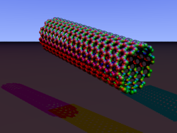
The wave is moving at right angles to the screen, towards you. I've greatly exaggerated the distance changes. For a realistic wave, even the giant distance between the Earth and the Sun would only change by a fraction of the diameter of a hydrogen atom. Tiny changes indeed.

How to detect something like this?

The first unsuccessful attempts to detect gravitational waves in the 1960s tried to measure how they make aluminum cylinders ring like a very soft bell. (Tragic story; Joe Weber [1919-2000], the pioneering physicist behind this, was sure he had detected gravitational waves in this way; after thorough analysis and replication attempts, community consensus emerged that he hadn't.)Afterwards, physicists came up with alternative scheme. Imagine that you are replacing the black point in the center of the previous animation with a detector, and the rightmost red particle with a laser light source. Now you send light pulses (represented here by fast red dots) from the light source to the detector; let's first look at this with the gravitational wave switched off:Simplified gravitational wave detector without gravitational waveEvery time a light pulse reaches the detector, an indicator light flashes yellow. The pulses are sent out regularly, they all travel at the same speed, hence they also reach the detector in regular intervals.If a gravitational wave passes through this system, again from the back and coming towards you, distances will change. Let us keep our camera trained on the detector, so the detector remains where it is. The changing distance to the light source, and also the changing distances between the light pulses, and some of the changes in distance between light pulses and detector or source, are due to the gravitational wave. Here is what that would look like (again, hugely exaggerated): The same simplified gravitational wave detector, but now with a gravitational wave passing through.Keep your eye on the blinking light, and you will see that its blinking is not so regular any more. Sometimes, the light blinks faster, sometimes slower. This is an effect of the gravitational wave. An effect by which we can hope to detect the gravitational wave."We" in this case are the radio astronomers working on what are known as Pulsar Timing Arrays. The sender of regular pulses are pulsars, rotating neutron stars sweeping a radio beam across our antennas like a cosmic lighthouse. The detectors are radio telescopes here on Earth. Detection is anything but easy. With a single pulsar, you'd need to track pulse arrival times with an accuracy of a few billionths of a second over half a year, and make sure you are not being fooled by various other sources of timing variations. So far, no gravitational waves have been detected in this way, although the radio astronomers are keeping at it.To see how gravitational wave detectors like LIGO work, we need to make things a little more complex.

Interferometric gravitational wave detectors: the set-up

Here is the basic set-up: Two mirrors, a receiver (or "light detector"), a light source and what is known as a beamsplitter: Basic setup for an interferometric gravitational wave detector
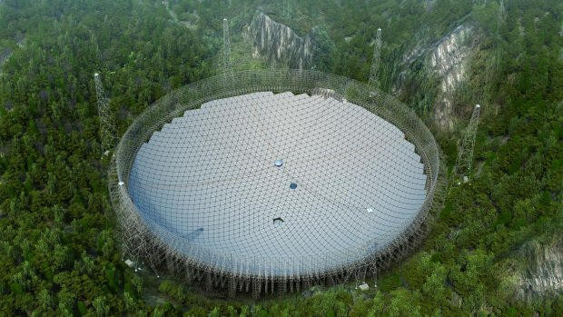
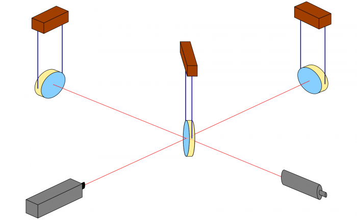
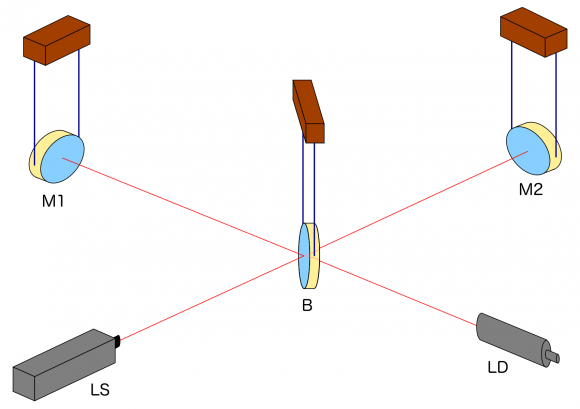
Light is sent into the detector from the (laser) light source LS to the beamsplitter B which, true to its name, sends half of the light on to the mirror M1 and lets the other half through to the mirror M2. At M1 and M2, respectively, the light is reflected back to the beam splitter. There, the light arriving from M1 (or M2) is split again, with half going towards the light detector LD, the other half back in the direction of the light source LS. We will ignore the latter half and pretend, for the sake of our simplified explanation, that all the light reaching B from M1 or M2 goes on to the light detector LD.(To avoid confusion, I will always refer to LD as the "light detector" and take the unqualified word "detector" to mean the whole setup.)This setup, by the way, is called a Michelson Interferometer. We'll see below why it is a good setup for gravitational wave detectors.In what follows, we will assume that the mirrors and the beam splitter, shown as being suspended, react to the gravitational wave in the same way freely floating particles would react. The key effects are between the mirrors and the beam splitter in what are called the two arms of the detector. Arm length is huge in today's detectors, running to a few kilometers. In comparison, light source and light detector are very close to the beamsplitter; changes of the distances between these three do not signify.

Light pulses in a gravitational wave detector

Next, let us see how light pulses run through this detector. Here is the same setup, seen from above: Simple interferometric gravitational wave detector, seen from above
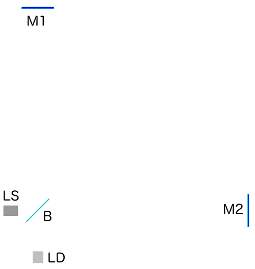
Light source LS, the two mirrors M1 and M2, the beamsplitter B and the light detector LD: all present and accounted for.Next, we let the light source emit light pulses. For greater clarity, I will make two artificial and unrealistic changes. I will send red and green pulses into the detector, representing the light that goes into the horizontal and the vertical arm, respectively. In reality, there is no distinction, just light apportioned at the beamsplitter. Light running towards M1 will be offset a little to the left, light coming back from M1 to the right, for better clarity. Same goes for M2. This, too, is different in a real detector. That said, here come the light pulses: Simplified interferometric gravitational wave detector with light running through both armsLight starts at the light source to the left. Light that has left the source together, travels together (so green and red pulses are side by side) until the beam splitter. The beam splitter then sends the green pulses on their upward journey and lets the red pulses pass on their way towards the mirror on the right. All the particles that arrive back at the beamsplitter after reflection at M1 or M2. At the beamsplitter, they are directed towards the light detector at the bottom.In this setup, the horizontal arm is slightly longer than the vertical arm. Red particles have to cover some extra distance. That is why they arrive at the detector a bit later, and we get an alternating rhythm: green, red, green, red, with equal distances in between. This will become important later on.Here is a diagram, a kind of registration strip, which shows the arrival times for red and green pulses at the light detector (time is measured in "animation frames"): Arrival times at the light detector of a simplified gravitational wave detector
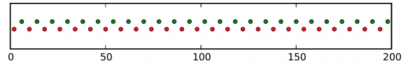
The pattern is clear: red and green pulses arrive evenly spaced, one after the other.

Bring on the gravitational wave!

Next, let's switch on our standard gravitational wave (exaggerated, passing through the screen towards you, and so on). Here is the result: Simple interferometric gravitational wave detector with a gravitational wave passing throughWe have trained our camera on the beamsplitter (so in our image, the beamsplitter doesn't move). We ignore any slight changes in distance between beamsplitter and light source/light detector. Instead, we focus on the mirrors M1 and M2, which change their distance from the beamsplitter just as we would expect from the earlier animations.Look at the way the pulses arrive at our light detector: sometimes red and green are almost evenly spaced, sometimes they close together. That is caused by the gravitational wave. Without the wave, we had strict regularity.Here is the corresponding "registration strip" diagram. You can see that at some times, the light pulses of each color are closer together, at others, farther apart: Arrival times for light pulses in a gravitational wave detector
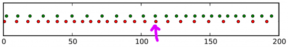
At the time I have marked with a hand-drawn arrow, red and green pulses arrive almost in unison!The pattern is markedly different from the scenario without a gravitational wave. Detect this change in the pattern, and you have detected the gravitational wave.

Running interference

If you've wondered why detectors like LIGO are called interferometric gravitational wave detectors, we will need to think about waves a bit more. If not, let me just state that detectors like LIGO use the wave properties of light to measure the changes in pulse arrival rate you have seen in the last animation. To skip the details, feel free to jump ahead to the last section, "...and now for something a thousand times more complicated."Light is a wave, with crests and troughs corresponding to maxima and minima of the electric and of the magnetic field. While the animations I have shown you track the propagation of light pulses, they can also be used to understand what happens to a light wave in the interferometer. Just assume that each of the moving red and green dots in the detector marks the position of a wave crest.Particles just add up. Take 2 particle and add 2 particles, and you will end up with 4 particles. But if you add up (combine, superimpose) waves, it depends. Sometimes, one wave plus another wave is indeed a bigger wave. Sometimes, it's a smaller wave, or no wave at all. And sometimes it's complicated.When two waves are in perfect sync, the crests of the one aligning with the crests of the other, and the troughs aligning, too, you indeed get a bigger wave. The following diagram shows at which times the different parts of two light waves arrive at the light detector, and how they add up. (I've placed a dot on top of each crest; that is what the dots where meant to signify, after all.) Constructive interference of light waves
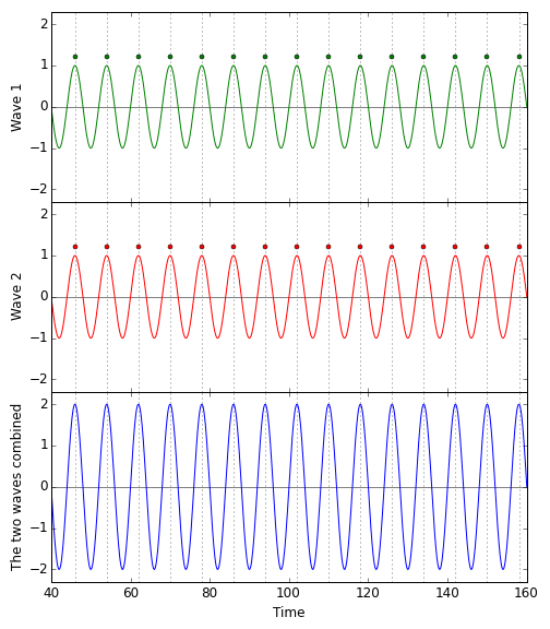
On top, the green wave, perfectly aligned with the red wave (which, for clarity, is shown directly below the green wave). Add the two waves up, and you will get the (markedly stronger) blue wave in the bottom panel.Not so if the two waves are maximally misaligned, the crests of each aligned with the troughs of the other. A crest and a trough cancel each other out. The sum of a wave and a maximally misaligned wave of equal strength is: no wave at all. Here is the corresponding diagram: Destructive interference of light waves
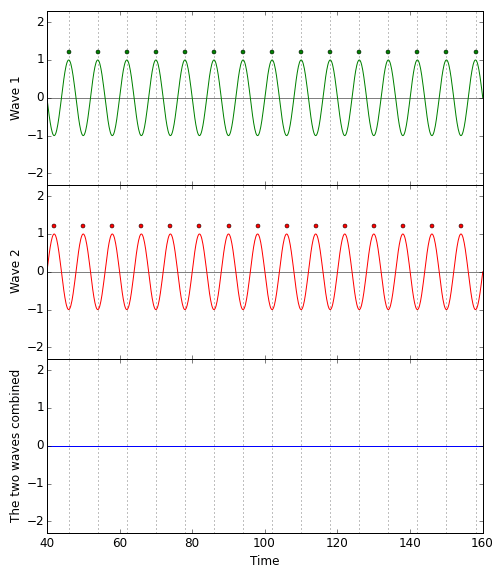
Recall that this was exactly the setup for our gravitational wave detector in the absence of gravitational waves: Red and green pulses with equal spacing; troughs of the one wave perfectly aligned with the crests of the other. The result: No light at the light detector. (For realistic gravitational wave detectors, that is almost true.)When a gravitational wave passes through the detector, the situation changes. Here is the corresponding pattern of pulse/wave crest arrival times for the animation above: Interference pattern for a gravitational wave passing through the simplified gravitational wave detector
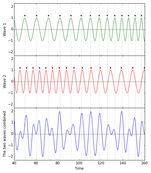
The blue pattern, which is the sum of the red and the green, is complex. But it is not a flat line. There is light at the light detector where there was no light before, and the cause of the change is the gravitational wave passing through.All in all, this makes a (highly simplified) version of how gravitational wave detectors such as LIGO work. Whatever the scientists will report this Thursday, it is based on light signals at the exit of such an interferometric detector.

And now for something a thousand times more complicated

Real gravitational wave detectors are, of course, much more complicated than that. I haven't even started talking about the many disturbances scientists need to take into account – and to suppress as far as possible. How do you suspend the mirrors so that (at least for certain gravitational waves) they will indeed be influenced as if they were freely floating particles? How do you prevent seismic noise, cars or trains in the wider neighborhood and so on from moving your mirrors a tiny little bit (either by vibrations or by their own gravity)? What about fluctuations of the laser light?Gravitational wave hunting is largely a hunt for noise, and for ways of suppressing that noise. The LIGO gravitational wave detectors and their kin are highly complex machines, with hundreds of control circuits, highly elaborate mirror suspensions, the most stable lasers known to physics (and some of the most high-powered). The technology has been contributed by numerous group from all over the world.But all this is taking us too far, and I refer you to the pages of the detectors and collaborations for additional information:LIGO pages at Caltech

Pages of the LIGO Scientific Collaboration

GEO 600 pages

VIRGO / EGO pages

You can find some further information about gravitational waves on the Einstein Online website:

Einstein Online: Spotlights on gravitational waves

Update: Gravitational Waves Discovered

The post Gravitational Wave Detectors: How They Work appeared first on Universe Today.

13 Feb 07:03

Calculator Built In Super Mario Level. Mamma Mia!

by Richard Baguley

Most people use the Super Mario Maker to, well, create Super Mario game levels. [Robin T] decided to try something a little different: building a working calculator. Several hundred hours later, he created the Cluttered Chaos Calculator, which definitely lives up to the name. What this Super Mario level contains is a 3-bit digital computer which can add two numbers between 0 and 7, all built from the various parts that the game offers. To use it, the player enters two numbers by jumping up in a grid, then they sit back and enjoy the ride as Mario is carried through the process, until it finally spits out the answer in a segment display.

It’s not going to be winning any supercomputer prizes, as it takes about two minutes to add the two digits. But it is still an incredibly impressive build, and shows what a dedicated hacker can do with a few simple tools and a spiny shell or two.

[Robin] explains the whole wonderful creation in a long Reddit post, detailing how he used the various mushrooms and bouncing parts to create a binary converter, four adders, an integer divider and a segment display and decoder that outputs the answer. He also put together a huge diagram that explains the logic flow (click for the larger version, but beware; it is about 6000 pixels wide).

mario-logic-full

He also covers some of the problems he found, such as how he was only able to do 3 bits because of the limitations of the game creator, and how he approached debugging this monstrosity (spoilers: he implemented checkpoints so that he could trigger parts of it and not have to wait for each test).


Filed under: computer hacks, nintendo hacks
13 Feb 06:24

Gatling Gun Shoots Arrows Out of Coke Bottles

by James Hobson

[JoergSprave] has done it again. His latest, most ridiculous weapon? A Gatling gun that fires crossbow bolts, using compressed air inside coke bottles — and an electric screwdriver.

For those of you not aware, [Joerg] is our favorite eccentric German maker, a purveyor of slingshots and all things ridiculous and weaponised. He runs the SlingShot Channel on YouTube, and has graced us with things like a slingshot cannon (firing 220lb balls!), a machete slingshot for the upcoming zombie apocalypse, and more.

Each coke bottle has a quick release pneumatic air valve, with a wooden lever attached to it to make opening the valve easier and quicker. The coke bottles are pressurized separately using an air compressor, but can also be filled using a bicycle pump — he got his hands on a pump capable of putting out 300 PSI! Word of safety though — you really don’t want to use coke bottles as pressure vessels — but [Joerge] is crazy so we’ll let it slide.

The bottles are then mounted on a ring which is rotated by an electric screwdriver. As the bottles spin around, the wood levers catch a curved surface, forcing the valves open, firing the arrows at approximately the same location every time. It’s surprisingly powerful, low-tech, and accurate.

[Thanks WickedMongoose!]


Filed under: weapons hacks
31 Jan 17:55

Dead Chickens and Fake Transistors in Medellin Colombia: HK4DEI's Micro 40 DSB Rig

by Bill Meara

Daniel HK4DEI wrote to report that page 149 of the SolderSmoke book was providing some solace and comfort as he struggled to get his version of Peter Parker's Micro 40 Double Sideband rig going.  He was having problems with the amplifier.   He was almost at the point of sacrificing chickens to Papa Legba.  I wished him luck and told him to hang in there. 

Elisa saw my e-mail to Daniel and complained that I hadn't given him the solution to his amplifier woes.  I tried to explain to her that there are sometimes things in this universe that are just UNKNOWABLE.  C.F. Rockey W9SCH (who alerted us in SPRAT 22 to the chicken sacrifice option) spoke of transistors that exhibit "quantum mechanical necromancy."  Rockey explained that when this happens, "The transistor simply turns up its toes and dies. Not even an Atomic Physicist can tell you why!"  


But Daniel persisted.  And he won the battle:

Hey Bill
Did you kill some chickens already? If you did, THANK YOU!  If you don't, then please enjoy a nice sancocho de gallina for me.

But seriously... guess what?
FAKE TRANSISTORS!!!!
I knew I couldn't be screwing everything up so badly and VK3YE's circuit couldn't be so wrong.
I was getting nuts trying to understand why it wasn't working, changing a single inductor could fry the final instantly or not getting any power out at all (?) also my final BD139 was getting extremely hot, and many of them died with no apparent reason (Page 149!!!!).
I ordered a "good" deal of BD139's and BD140's combo for an incredible low price from [A WEB SITE], I've ordered many *apparently good components from that site with no problems so far... mainly resistors and capacitors. Having tried everything to get my circuit working and after some quick online search about fake transistors from china my suspicions grew considerably and I remembered some -other- BD139's I had ordered from Amazon some time ago.
I proceeded to solder the new transistors in place in my PA and Bingo! No more heating of the final and about the expected 0.5W out from my first DSB homebrew rig. I quickly reported to a fellow homebrewer in a local net and the report was amazing! 59 +10, the final transistor was comfortably warm to the touch and my mind could finally rest... lesson learned! What an electromagnetic achievement!
Just wanted to share my success Bill and thank you again for you book and you kind response.
Please say hi to Elisa and the Cristalinhos from a fellow Latin friend.
Clear Skies.
73/72 from Colombia!
Daniel
HK4DEI


If you like the blog you'll like my book: "SolderSmoke -- Global Adventures in Wireless Electronics" Available in print, Kindle,and I-pad editions. http://soldersmoke.com/book.htm
27 Jan 15:07

I Built Myself a 16×20-Inch Camera in 10 Hours

by Gerrit Coetzee

[Giles Clement] was avoiding work in a bar, nursing a pint, and doodling a sketch for a camera. He looked at his sketch, thought, “gee, that looks better than answering emails,” and called his friend. An hour later they were at home depot buying supplies, and ten hours of furious work later, they had a camera. Nothing gets a project done like avoiding work! (See it all happen before your eyes in the video below the break.)

The camera is built around a 500mm f/4.5 Goerz Dogmar lens from around 1918 and was apparently used for aerial recon out of blimps. The frame of the camera is pine and plywood. [Giles] had heard that building the bellows for these cameras had taken other hobbyists months and thousands of dollars. Rather than elaborately folded fabric, he supported his 6 mil plastic bellows on telescoping rigid rods. To view the image while he’s focusing it, he sanded a plate of glass with 100 grit sandpaper to serve as a view screen.

Once the camera was completed, they prepared the plates and exposed photos. The first step, from what we could tell, was to disregard all chemical safety practices. The second step was pouring a substance called collodion on an unsanded glass plate and tilting the plate back and forth until the whole plate had an even coat on it. Then it was put in a bath of silver nitrate to sensitize. Once sensitized the plate was placed in the frame of the focused camera and an astonishing amount of strobe light emitted. After that it’s back to the chemical baths for more safety hazards. The whole process has to be done under fifteen minutes or the plate cures before it can be used. The photos that come out are seriously cool. It’s no wonder these old styles of photography have seen a comeback.

[via HackerNews]


Filed under: classic hacks
16 Jan 19:12

http://onetuberadio.com/2016/01/08/5232/

by clem.law@usa.net

1916HeadAsReproducer

The photo is self-explanatory.  You don’t need any fancy electronics to listen to your phonograph.  All you need is a needle held between your teeth, and the music will play loudly in your head.  For more details, see this month’s issue of Electrical Experimenter, a hundred years ago.

06 Jan 01:39

Four new elements added to periodic table, filling out the chart’s seventh row

by Rebecca Houlihan

NewImage

Four new elements discovered and added to the periodic table. via geekwire

The scientific body in charge of chemistry’s periodic table has verified the discoveries of four elements – completing the seventh row of the century-old chart.

For now, the elements are known as ununtrium (Element 113), ununpentium (Element 115), ununseptium (Element 117) and ununoctium (Element 118). It’ll be up to the newly recognized discoverers to propose the officlal names. The numbers denote how many protons are in the element’s nucleus.

Read more