Shared posts

29 Jul 08:39

Fast branchless RGB to HSV conversion in GLSL

by sam

Some time ago I devised an original algorithm to convert from RGB to HSV using very few CPU instructions and I wrote a small article about it.

When looking for a GLSL or HLSL conversion routine, I have found implementations of my own algorithm. However they were almost all straightforward, failing to take full advantage of the GPU’s advanced swizzling features.

So here it is, the best version I could come up with:

vec3 rgb2hsv(vec3 c)
{
    vec4 K = vec4(0.0, -1.0 / 3.0, 2.0 / 3.0, -1.0);
    vec4 p = mix(vec4(c.bg, K.wz), vec4(c.gb, K.xy), step(c.b, c.g));
    vec4 q = mix(vec4(p.xyw, c.r), vec4(c.r, p.yzx), step(p.x, c.r));
    float d = q.x - min(q.w, q.y);
    float e = 1.0e-10;
    return vec3(abs(q.z + (q.w - q.y) / (6.0 * d + e)), d / (q.x + e), q.x);
}

Update: ​Emil Persson suggests using the ternary operator explicitly to force compilers into using a fast conditional move instruction:

    vec4 p = c.g < c.b ? vec4(c.bg, K.wz) : vec4(c.gb, K.xy);
    vec4 q = c.r < p.x ? vec4(p.xyw, c.r) : vec4(c.r, p.yzx);

And because a lot of people get it wrong, too, here is the reverse operation in GLSL. It is the algorithm almost everyone uses (or should use):

vec3 hsv2rgb(vec3 c)
{
    vec4 K = vec4(1.0, 2.0 / 3.0, 1.0 / 3.0, 3.0);
    vec3 p = abs(fract(c.xxx + K.xyz) * 6.0 - K.www);
    return c.z * mix(K.xxx, clamp(p - K.xxx, 0.0, 1.0), c.y);
}

Porting to HLSL is straightforward: replace vec3 and vec4 with float3 and float4, mix with lerp, fract with frac, and clamp(…, 0.0, 1.0) with saturate(…).

21 Jul 20:58

Advanced terrain texture splatting

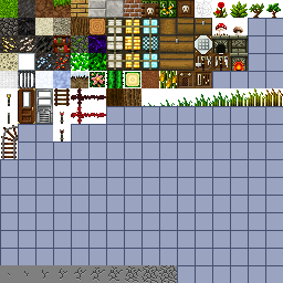
Having trouble getting your terrain textures to blend properly? This short tutorial, with code samples, will put you on track. ...

17 Jul 12:28

Lazy Theta*: Faster Any-Angle Path Planning

by Alex J. Champandard

(Copyright © AiGameDev.com, 2013.)

Lazy Theta*: Faster Any-Angle Path Planning

This article was written by Alex Nash, a software engineer at Northrop Grumman with a Ph.D. from the University of Southern California, specializing in path planning for video games and robotics. You can contact him by email <alexwnash at gmail.com>.

In path finding, A*-like algorithms rely on a discrete navigation representation such as grids or navigation meshes » Click here to view this embedded content., » Click here to view this embedded content., » Click here to view this embedded content., which then requires path smoothing as a post-process. Any-angle path planning algorithms tackle both these tasks at the same time, for instance the Theta* algorithm that selectively performs line-of-sight calculations while path finding. This article digs into optimizations of Theta* reducing the number of line-of-sight checks required and optimizing the algorithm.

Grid Paths

Figure 1: Grid Paths: Square Grid (left), Navigation Mesh adapted from » Click here to view this embedded content. (center) and Cubic Grid (right)

Any-Angle Paths

Figure 2: Any-Angle Paths: Square Grid (left), Navigation Mesh adapted from » Click here to view this embedded content. (center) and Cubic Grid (right)

Any-angle path planning algoirthms propagate information along graph edges (to achieve short runtimes), but do not constrain paths to be formed by graph edges (to find short "any-angle" paths). This can be seen by comparing Figure 1, which depicts grid paths, with Figure 2, which depicts any-angle paths. One such algorithm, Theta* » Click here to view this embedded content.» Click here to view this embedded content., that we discussed in our previous article, finds short and realistic looking paths (the author suggests you take a quick look at the Theta* article before reading this one). Theta* can be slower than A* and A* with a post processing technique because it performs a line-of-sight check for each unexpanded visible neighbor of each expanded vertex. As a result, on large grids, Theta* can perform lots of line-of-sight checks and line-of-sight checks can be time consuming.

Many Line-of-sight Checks

Figure 3: Line-of-sight checks performed by Theta* (left) and Lazy Theta* (right)

Luckily, it turns out that Theta* performs more line-of-sight checks than it has to. If Theta* performs a line-of-sight check between a vertex s and its parent, and vertex s is never expanded, then it is wasted computation. Given that that is the case, Theta* might be a little too eager to perform line-sight checks because it peforms a line-of-sight check for each unexpanded visible neighbor of each expanded vertex even though many of those vertices may never be expanded. Therefore, the question is, how can Theta* take a more laid back approach to performing line-of-sight checks while still finding short and realistic looking paths?

This was the topic of a recent paper » Click here to view this embedded content. that I co-wrote with Sven Koenig and Craig Tovey and which was presented at AAAI'10. In the paper, we presented a new any-angle path planning algorithm, called Lazy Theta*. Lazy Theta* is a variant of Theta* and thus it propagates information along graph edges (to achieve a short runtime) without constraining the paths to graph edges (to find "any-angle" paths). Like Theta*, Lazy Theta* is simple (to understand and to implement), fast and finds short and realistic looking paths. In fact, the pseudo code for Lazy Theta* has only four more lines than the pseudo code for A* (red lines in Figure 4). Lazy Theta* is faster than Theta* because it takes a much more laid back approach as to when it peforms line-of-sight checks and yet it still finds short and realistic looking paths. We show experimentally that Lazy Theta* finds paths faster than Theta*, with significantly fewer line-of-sight-checks than Theta* and without an increase in path length. For example, in the simple search depicted in Figure 3, both Theta* and Lazy Theta* find the same path, but Theta* performs 15 line-of-sight checks while Lazy Theta* performs only 4 line-of-sight checks. We also introduce Lazy Theta* with Optimizations. Lazy Theta* with Optimizations finds paths whose lengths are similar to those found by Lazy Theta*, however it often performs more than one order of magnitude fewer line-of-sight checks (and vertex expansions).

For simplicity, this article will focus on square grids in which a two-dimensional continuous environment is discretized into square cells that are either blocked (grey) or unblocked (white). Furthermore, we map vertices to the corners of cells as opposed to the centers of cells. Neither of these two assumptions is required for Theta*, Lazy Theta* or Lazy Theta* with Optimizations to function correctly. Our goal is to find a short and realistic looking path from the start location to the goal location (both at the corners of cells) that does not pass through blocked cells, as shown in Figure 2 (left).

We assume an eight-neighbor grid throughout this article, where V is the set of all grid vertices, sstart in V is the start vertex of the search, and sgoal in V is the goal vertex of the search. c(s,s') is the straight line distance between vertices s and s', and lineofsight(s,s') is true if and only if they have line-of-sight. Psuedo code for lineofsight can be found here. nghbrvis(s) in V is the set of neighbors of vertex s in V that have line-of-sight to s. Unless, otherwise stated all algorithms use the straight line distances as h-values.

Lazy Theta*

Lazy Theta* psuedo code

Figure 4: Pseudo Code of A* (left), Theta* (center) and Lazy Theta* (right)

Lazy Theta* is shown in Figure 4 (right)» Click here to view this embedded content. along with Theta* (center) and A* (left). Our inspiration is provided by probabilistic road maps (PRMs), where lazy evaluation has been used to reduce the number of line-of-sight checks (collision checks) by delaying them until they are absolutely necessary » Click here to view this embedded content..

Theta* updates the g-value and parent of an unexpanded visible neighbor s′ of a vertex s in procedure ComputeCost by considering Path 1 and Path 2:

It considers Path 2 if s′ and parent(s) have line-of-sight. Otherwise, it considers Path 1. Lazy Theta* optimistically assumes that s′ and parent(s) have line-of-sight without performing a line-of-sight check (Line 30 (right)). Thus, it delays the line-of-sight check and considers only Path 2. This assumption may of course be incorrect (Figure 5 (right)). Therefore, Lazy Theta* performs the line-of-sight check in procedure SetVertex immediately before expanding vertex s′. If s′ and parent(s′) indeed have line-of-sight (Line 35 (right)), then the assumption was correct and Lazy Theta* does not change the g-value and parent of s′. If s′ and parent(s′) do not have line-of-sight, then Lazy Theta* updates the g-value and parent of s′ according to Path 1 by considering the path from sstart to each expanded visible neighbor s′′ of s′ and from s′′ to s′ in a straight line and choosing the shortest such path (Lines 37 and 38 (right)). We know that s′ has at least one expanded visible neighbor because s′ was added to the open list when Lazy Theta* expanded such a neighbor.

Lazy Theta* example

Figure 5: Lazy Theta* updates a vertex according to Path 2 without a line-of-sight check.

Lazy Theta* trace 1

Figure 6: Example Trace of Lazy Theta*

Figure 6 shows a complete trace of Lazy Theta*. Each vertex is labeled with an arrow pointing to its parent vertex. The hollow red circle indicates which vertex is currently being expanded. When B3 with parent A4 is being expanded, B2 is an unexpanded visible neighbor of B3. Lazy Theta* optimistically assumes that B2 has line-of-sight to A4. B2 is expanded next. Since B2 and A4 do not have line-of-sight, Lazy Theta* updates the g-value and parent of B2 according to Path 1 by considering the paths from the start vertex to B3 to each expanded visible neighbor s′′ of B2 (namely, B3) and from s′′ to B2 in a straight line. Lazy Theta* sets the parent of B2 to B3 since the path from A4 to B3 and from B3 to B2 in a straight line is the shortest such path. In this example, Lazy Theta* and Theta* find the same path from the start vertex A4 to the goal vertex C1, but Lazy Theta* performs 4 line-of-sight checks, while Theta* performs 13 line-of-sight checks.

While, Lazy Theta* provides a better tradeoff with respect to path length and runtime than Theta* it can still be slower than A* with Post Smoothing because it can perform more vertex expansions and more line-of-sight checks. To address this shortcoming we introduced Lazy Theta* with Optimizations. Lazy Theta* with Optimizations was covered in my dissertation » Click here to view this embedded content..

Lazy Theta* with Optimizations

So far, Theta* and Lazy Theta* have used consistent h-values (that is, h-values that obey the triangle inequality), namely the straight line distances. A* with consistent h-values finds paths of the same length no matter how small or large the h-values are. A* with inconsistent h-values is able to find longer paths at a decrease in runtime by using weighted h-values with weights greater than one. We therefore now discuss a variant of Lazy Theta*» Click here to view this embedded content., Lazy Theta* with Optimizations, that can find longer paths at a decrease in runtime by using weighted h-values with weights greater than one. Lazy Theta* with Optimizations uses the h-values h(s) = w * c(s, sgoal) for a given weight w > 1 and thus is similar to Weighted A*. Weighted A* with w > 1 can significantly reduce runtimes without a significant increase in path lengths » Click here to view this embedded content..

In this section, we show that, by using weighted h-values with weights greater than one, Lazy Theta* can find paths faster without a significant increase in the lengths of the resulting paths. A* searches with inconsistent h-values typically expand fewer vertices, but often find longer paths because every vertex omitted from a search explicitly omits a potential path. If a vertex s is not expanded during a search then a visible neighbor s′ of vertex s cannot have vertex s as its parent and thus vertex s cannot be on any path. For Lazy Theta*, the effect of not expanding a vertex during the search is different because Lazy Theta* considers both Path 1 and Path 2. If a vertex s is not expanded during a search, then a visible neighbor s′ of vertex s cannot have vertex s as its parent, but vertex s′ can still potentially have parent parent(s) (that is, the parent that vertex s would have had if vertex s had been expanded) due to Path 2. In fact, it is likely that several other vertices have parent parent(s) from which vertex s′ can inherit parent parent(s). In other words, Lazy Theta* with Optimizations may be able to find short paths while performing many fewer vertex expansions (and thus many fewer line-of-sight checks).

Lazy Theta* Optimizations

Figure 7: Lazy Theta* with w=1 (left) and Lazy Theta* with w=1.1 (right)

Figure 7 shows an example in which Lazy Theta* with Optimizations provides a far better tradeoff with respect to path length and runtime. In Figure 7 (left), a Lazy Theta* search with w=1 was performed and a purple dot was placed on every expanded vertex. Similarly, in Figure 7 (right), a Lazy Theta* search with w=1.1 was performed and a purple dot was placed on every expanded vertex. The Lazy Theta* search with w=1 performed more than one order of magnitude more line-of-sight checks AND vertex expansions than the Lazy Theta* search with w=1.1. However, the ratio of the path lengths is only 1.002 (not depicted in the figure). While there are environments, such those with a cul-de-sac, in which the tradeoff with respect to path length and runtime is not quite as good for Lazy Theta* with Optimizations, there are many environments in which it provides an excellent tradeoff with respect to path length and runtime.

Analysis

While Theta* found paths whose lengths were nearly identical to the lengths of the truly shortest paths (see our previous article) it did so with a longer runtime than A* and A* with Post Smoothing. This was because Theta* performed both more vertex expansions and more line-of-sight checks than A* and A* with Post Smoothing, respectively. To address this shortcoming we introduced Lazy Theta* and Lazy Theta* with Optimizations. We performed an extensive analysis using both small and large square grids from Bioware's popular RPG Baldur’s Gate (game maps) and square grids with given percentages of randomly blocked cells (random maps). We found that on average the ratio of the lengths of the paths found by Theta* and Lazy Theta* was 1.002 on random maps, however Lazy Theta* peformed one third the number of line-of-sight checks that Theta* performed. As the number of line-of-sight checks and the runtime of line-of-sight checks increases so does the runtime advantage of Lazy Theta* over Theta*. For example, on 26-neighbor cubic grids Lazy Theta* performs one order of magnitude fewer line-of-sight checks than Theta* and can be nearly twice as fast. Lazy Theta* with Optimizations can provide and even better tradeoff with respect to the runtime of the search and the length of the resulting path. We found that on average the ratio of the lengths of the paths found by Theta* and Lazy Theta* with Optimizations was 1.006 on random maps, however Lazy Theta* with Optimizations peformed two orders of magnitude fewer line-of-sight checks and more than one order of magnitude fewer vertex expansions. In fact, in certain environments, Lazy Theta* with Optimizations performed the same number of vertex expansions as A* with the octile heuristic (a version of A* that can be extremely efficient) and the same number of line-of-sight checks as A* with Post Smoothing, while finding paths that were 2% shorter and more realistic looking.

Concluding Remarks

I hope this article will serve to highlight the usefulness of any-angle path planning methods for efficiently finding short and realistic looking paths. For more information on Theta*, Lazy Theta* and Lazy Theta* with Optimizations I suggest taking a look at the original papers » Click here to view this embedded content.» Click here to view this embedded content.,» Click here to view this embedded content. or visiting our any-angle path planning web page. If you like Theta*, Lazy Theta* and Lazy Theta* with Optimizations, you may also like Field D* » Click here to view this embedded content., Block A* » Click here to view this embedded content. and Accelerated A* » Click here to view this embedded content..

If you have specific questions or comments regarding anything described in this article, please feel free to contact me.

Footnotes

» Click here to view this embedded content. open.Insert(s,x) inserts vertex s with key x into open. open.Remove(s) removes vertex s from open. open.Pop() removes a vertex with the smallest key from open and returns it.

» Click here to view this embedded content. These same optimizations can be used for Theta* as well, however they are less effective because Theta* performs many more line-of-sight checks per vertex expansion.

References

              Theta*: Any-Angle Path Planning on Grids
              » Click here to view this embedded content. A. Nash, K. Daniel, S. Koenig and A. Felner (Download PDF)
              (2007) Proceedings of the AAAI Conference on Artificial Intelligence
            
              Theta*: Any-Angle Path Planning on Grids
              » Click here to view this embedded content. A. Nash, K. Daniel, S. Koenig and A. Felner (Download PDF)
              (2010) Journal of Artificial Intelligence Research
            
              Lazy Theta*: Any-Angle Path Planning and Path Length Analysis in 3D
              » Click here to view this embedded content. A. Nash and S. Koenig and C. Tovey (Download PDF)
              (2010) Proceedings of the AAAI Conference on Artificial Intelligence
            
              Any-Angle Path Planning
              » Click here to view this embedded content. A. Nash (Download PDF)
              (2012) Dissertation
            
              Comparison of Different Grid Abstractions for Pathfinding on Maps
              » Click here to view this embedded content. Y. Bjornsson, M. Enzenberger, R. Holte, J. Schaeffer and P. Yap (Download PDF)
              (2003) Proceedings of the International Joint Conference on Artificial Intelligence
            
              AI Game Programming Wisdom 2: Search Space Representations
              » Click here to view this embedded content. P. Tozour
              (2004) Charles River Media, pp. 85-102
            
              Game Programming Gems: A* Aesthetic Optimizations
              » Click here to view this embedded content. S. Rabin
              (2000) Charles River Media, pp. 264-271
            
              Using Interpolation to Improve Path Planning: The Field D* Algorithm
              » Click here to view this embedded content. D. Ferguson and A. Stentz (Download FILE)
              (2006) Journal of Field Robotics, Volume 23, Issue 2, pp. 79-101
            
              Grid-Based Path-Finding
              » Click here to view this embedded content. P. Yap (Download FILE)
              (2002) Proceedings of the Canadian Conference on Artificial Intelligence, pp. 44-55
            
              Formal Basis for the Heuristic Determination of Minimum Cost Paths
              » Click here to view this embedded content. P.E. Hart, N.J Nilsson, B. Raphael (Download FILE)
              (1968)  IEEE Transactions on Systems Science and Cybernetics, Volume 4, Issue 2
            
              Amit's Game Programming Information
              » Click here to view this embedded content. (2000) A. Patel (View Online)
            
              Path Planning Using Lazy PRM
              » Click here to view this embedded content. R. Bohlin and L.Kavraki (Download FILE)
              (2000) Proceedings of the IEEE Transactions on Robotics and Automation
            
              Block A*: Database-Driven Search with Applications in Any-angle Path-Planning
              » Click here to view this embedded content. P. Yap and N. Burch and R. Holte and J. Schaeffer (Download PDF)
              (2011) Proceedings of the AAAI Conference on Artificial Intelligence
            
              Linear-space best-first searc
              » Click here to view this embedded content. R. Korf
              (1993) Journal of Artificial Intelligence
            
              Accelerated A* Path Planning
              » Click here to view this embedded content. D. Sislak and P. Volf and M. Pechoucek (Download FILE)
              (2009) Proceedings of AAMAS Conference on Autonomous Agents & Multiagent Systems 
            
17 Jul 12:28

Dual depth buffering for translucency rendering

by Kostas Anagnostou

A nice and cheap technique to approximate translucency was presented some time ago at GDC. The original algorithm depended on calculating the “thickness” of the model offline and baking it in a texture (or maybe vertices). Dynamically calculating thickness is often more appealing though since, as in reality, the perceived thickness of an object depends on the view point (or the light’s viewpoint) and also it is easier to capture the thickness of varying volumetric bodies such as smoke and hair.

An easy way to dynamically calculate thickness is render the same scene twice store the backfacing triangles’ depth in one buffer and the frontfacing ones’ in another and taking the difference of the values per pixel (implementing two-layer depth peeling in essence). This method works well but it has the disadvantage of rendering the scene at least one extra time.

Looking for ways to improve dynamic thickness calculation, I came across a dual depth buffering technique in ShaderX6 (“Computing Per-Pixel Object Thickness in a Single Render Pass” by Christopher Oat and Thorsten Scheuermann) which manages to calculate the thickness of an object/volume in one pass. The main idea behind this technique is to turn culling off, enable alpha blending by setting the source and destination blend to One and the blend operation to Min and store depth in the Red channel and 1-depth in the Green channel. That way we can calculate the thickness of an object in the main pass as thickness = (1 – Green) – Red. The depth can be either linear or perspectively divided (by w), although the latter will make the calculated thickness vary according to distance to the camera.

The following screenshots demonstrate this. The “whiter” the image the thicker it is. We can see that the thickness varies depending on the viewpoint (you can see that on the torso and the head for example)

dualdepth1

dualdepth2

This technique works nicely for calculating the thickness of volumetric bodies such as smoke and hair, but not that well for solid objects with large depth complexity as it tends to overestimate the thickness. You can see this in the above images (the leaves in front of the statue are very white) and the following couple of images demonstrate this problem in practice.

dualdepth_trans1

The model is rendered with the “fake” translucency effect mentioned above and by calculating the thickness dynamically with a dual depth buffer. We also placed a light source behind the statue. Viewing the statue from the front it looks ok and we can see the light propagating through the model at less thick areas (like the arm). If we rotate the statue so as to place the leaves between the body and the light we can see them through the statue (due to the overestimation of thickness it absorbs more light than it should and this areas appear darker).

dualdepth_trans2

This method is clearly not ideal for solid, complex, objects but we can modify slightly and improve it. Ideally I would like to know the thickness of the first solid part of the model as the ray travels from the camera into the scene.

So instead of storing (depth, 1-depth) in the thickness rendertarget for all rendered pixels I make a distinction between front facing the back facing samples and store the depth as such:


if ( frontfacing )
{
return float4( depth, 1, 0, 1);
}
else
{
return float4( 1, depth, 0, 1);
}

The blending mode remains the same (Min). This way I get the distance of the first front facing and the first backfacing triangle sample along the view ray and calculating the thickness is a matter of subtracting them: thickness = Green – Red.

The following two images demonstrate the effect:

dualdepth_modified_trans1

dualdepth_modified_trans2

The overall effect is the same as previously but now the leaves are no longer visible through the body of the statue since they are not taken into account when calculating the thickness at the specific pixels.

In summary, dual depth buffering is a nice technique to calculate the thickness of volumetric bodies and simple solid objects and with a slight modification it can be used to render more complicated models as well.


11 Jul 13:44

Présentation d'une publication: Sorted Deferred Shading for Production Path Tracing

by Narann

Sorted_Deferred_Shading_tn.pngCe billet est une présentation très succincte d'une publication de Walt Disney Animation Studios datant de 2013 visant à expliquer les tenants et aboutissants du "tri" des rayons et shading points avant leur calcul: Sorted Deferred Shading for Production Path Tracing.

Je ne rentrerais pas dans les détails et un développeur un peu à l'aise avec le raytracing tirera surement beaucoup plus d'informations du papier original. :siffle:

Introduction

Tout d'abord pourquoi parler de ça sur ce blog? :reflechi:

Comme vous avez surement pu le constater, je ne suis plus très actif. Sachez que ce n'est pas uniquement un manque de temps mais surtout de sujets à aborder.

En effet, au fils des années j'ai commencé à travailler sur des problématiques de plus en plus complexes et de moins en moins génériques. Il y avait donc très peu d’intérêt d'aborder les sujets ici.

J'ai un certain nombre de billets que j'ai commencé sans jamais les finir car les sujets abordés n'étaient soit pas intéressants (mon point du vue sur la vague des "logiciels de rendu") sois trop spécifiques (il n'est pas évident d'aborder les technologies maisons des studios :cayMal: ).

Bref, ce n'est pas pour autant que j'ai chaumé et j'ai emmagasiné un bon paquet d'infos, de connaissances que je commence à maitriser, en tous cas, suffisamment pour en parler. :laClasse:

L'idée m'est donc venue de vous parler de différentes publications (papers en anglais) dont vous avez surement déjà dû voir ou entendre parler, leur sortie étant très florissante pendant la période du Siggraph. :jdicajdirien:

Maintenant, pourquoi cette publication là en particulier?

Et bien parce que depuis quelques années l'idée que le full raytracing "va tout simplifier" s'est généralisée. Le maitre incontesté de cette philosophie est sans conteste Arnold à qui on pourrait presque reprocher son approche quasi religieuse, mais le virage abrupt de Renderman vers du full raytrace tend à lui donner raison. :pasClasse:

Et pourtant. Non, tout n'est pas rose au pays du full raytrace. Car si de nouvelles choses sont possibles, de nouvelles problématiques apparaissent et oui, il faut "tricher". Le rayswitch devient la norme et tout moyen visant à gagner du temps est mis à profit, car c'est bien le rapport temps/qualité qui détermine l'efficacité d'un moteur, et la course à la puissance a aussi ses limites. :papi:

Cette publication est intéressante car elle permet, de par la problématique qu'elle aborde (GI raytrace) de comprendre les défis et limites que peuvent/vont rencontrer les moteurs de rendu modernes.

Avant propos

Avant de commencer je voudrais préciser quelques points techniques importants. Ces notions ne sont pas forcément très connu des graphistes, pourtant je pense qu'elle ont beaucoup de sens, même à notre échelle.

Rayon cohérent/incohérent

Un terme fréquemment utilisé quand on parle d'optimisation du raytracing est cohérent/incohérent mais doit se comprendre comme qui varie peu/qui varie beaucoup/presque aléatoire.

coherent_incoherent_rays.jpg

Ces images sont tirées du très instructif article de Intel expliquant le fonctionnement de Embree: Embree: Photo-Realistic Ray Tracing Kernels. Pdf ici.

  • A gauche: Ce sont des rayons cohérents. Ils partent d'un même point et vont dans une direction particulière (même si cette direction est plus ou moins "ouverte"). Le nombre d'objets que vont toucher ces rayons est faible.
  • A droite: Ce sont des rayons incohérents. Ils vont et viennent de toutes les directions. Bien entendu, le nombre d'objets que vont toucher ces rayons est important.

Vous allez très vite comprendre le pourquoi du comment. :sourit:

Rays et Shading Points

En raytracing on fait souvent la distinction entre le lancer de rayons en lui même (savoir quelle géométrie le rayon va toucher dans la scène) et le shading du point (le fait de calculer la couleur, la reflection, tout ce qui est lié au matérial sur ladite géométrie).

Ce sont deux étapes très différentes:

schema_shading_point.png

Out-of-core

Le terme out-of-core est un terme que l'on rencontre souvent dans les calculs massivement distribués. La page Wikipedia explique bien le principe mais en gros, core est un ancien terme pour désigner la mémoire vive. Out-of-core fait donc référence à des calculs sur des données qui ne sont pas stockées dans la mémoire vive mais directement sur le disque.

Pour être efficace, un calcul out-of-core doit lire le minimum d'information sur le disque, et donc, les informations les plus pertinentes.

Si vous comprenez ces notions, la suite va vous sembler évidente. :dentcasse:

Traduction

Toute bonne publication commence par la partie la plus courte et la plus simple à comprendre: Abstract. Même si ce genre de lecture ne vous fait pas rêver, je vous encourage à la lire si vous vous intéressez un temps soit peu à la technique.

Le principe est de résumer, aussi simplement que possible, en quelques phrases, ce que présente la publication.

Abstract

L'illumination globale (GI) en lancé de rayon se généralise dans le rendu de production mais l'incohérence des rayons secondaires limite son utilisation à des scènes qui peuvent être placées intégralement en mémoire.

L'incohérence du shading entraine également d'importants soucis de performance lors de l'utilisation de nombreuses (et lourdes) textures qui oblige le moteur de rendu à recourir aux caches d'irradiance, de radiosité, et autres moyens pour diminuer le cout du shading.

Malheureusement, cette mise en cache:

  • Complique le travail du graphiste
  • Est difficile à paralléliser efficacement
  • Occupe une précieuse mémoire.
  • Et pire, ces caches impliquent une approximations qui altère la qualité.

Dans cette publication, nous présentons une nouvelle structure de path tracing qui évite ces compromis. Nous organisons les rayons en gros paquets, potentiellement hors du core, pour assurer la cohérence des rayon lancés.

Nous retardons le shading des points touchés par les rayons jusqu'à ce que nous les ayons trié, ce qui permet un shading cohérent et évite d'avoir recours à des caches.

Et voilà pour Abstract!

Avouez que ce n'est pas non plus la misère à comprendre. :seSentCon:

On enchaine avec l'introduction qui résume grosso modo ce que présente Abstract.

Introduction

La GI en path-tracing offre de nombreux avantage en rendu de production: Un éclairage plus riche, plus plausible avec moins de lights et évite la lourde gestion des données liées aux point clouds (PTC) et aux deep map shadows.

Bien que cette approche offre une meilleure image et une productivité accrue, les performances se dégrade de manière importante à mesure que la géométrie et les textures dépassent la capacité mémoire disponible.

Ainsi, les moteurs de rendu de production existants s'évertuent à lancer le moins de rayons possible et à calculer le moins de points de shading possible, privilégiant l'utilisation de caches d'éclairage/de shading et de géométrie instanciées. Mais ces mesures gênent le travail des graphistes.

A mesure que la recherche améliore l'intersection rayon/géométrie, le calcul de shading points incohérent devient un problème de plus en plus conséquent.

En particulier, l'accès incohérent à d'énormes textures de production entraine de fréquents cache-misses (à traduire: "Pas dispo dans le cache de texture? S'pas grave, on reload!") provoquant des pauses importantes due à la latence d'accès mémoire/disque/réseaux durant le calcul.

Les caches d'irradiance et de radiosité tentent de minimiser cela, bien que leur non-directionalité inhérente ne les rendent efficace que pour des surfaces parfaitement diffuses. (ndt: Par "non-directionnalité", comprenez qu'on ne peut stocker l'irradiance d'une surface réfléchissante, qui "varie en fonction de la direction", miroir etc... Le chercheur semble toutefois oublier qu'une irradiance est tout à fait "stockable" sous la forme d'une spherical harmonique, ce qui permet de palier à ce problème).

Par conséquent, il est d'usage de séparer les techniques en fonction du type de rayon à calculer (diffus, spéculaires et caustiques) ce qui complique encore le travail des graphistes.

Pire encore, ces approches sont difficiles à adapter à des architectures multi-core à cause de la synchronisation, l'effet NUMA (le fait d'aller chercher des informations un peu partout dans la mémoire diminue drastiquement ces performances) et l'équilibrage de la charge (load-balancing).

De fait, il est préférable d'éviter les caches et privilégier un shading cohérent.

Dans cette publication, nous présentons un ray-tracer continu capable d'effectuer plusieurs rebonds de GI dans une scène de production sans recourir à des caches de shading ou des instances.

Pour y parvenir, nous introduisons une nouvelle approche de tri de rayon en deux étapes.

Dans un premier temps, nous organisons les rayons en gros paquets, potentiellement hors du core (stocké sur disque donc), pour s'assurer de leur cohérence.

Travailler avec de gros paquets est essentiel pour extraire les groupes de rayons cohérent d'une scène complexe.

Dans un second temps, nous trions les rayons ayants touchés (les fameux ray hits) pour calculer les shading des points en utilisant les textures hors du core.

Pour chaque lot, nous réalisons un shading parfaitement cohérent avec des lectures de textures séquentielles, ce qui élimine la nécessité d'un cache de texture.

Notre approche est simple à implémenter et compatible avec la plupart des techniques de casting de scène.

Nous démontrons l'efficacité de notre tri en deux étapes combiné au paquets de rayons hors du core et comparons nos résultats avec les deux principaux ray-tracers de production: PhotoRealistic RenderMan (hum... :trollface: ) de Pixar et Arnold de Solid Angle.

Je m’arrête là, pour plus d'explications, il faut lire la publication! :sauteJoie:

Explications

Ce qu'explique cette publication c'est que le fait d'avoir beaucoup de rayons incohérents va nécessiter un load de quasiment toute la scène pour calculer les intersections des rayons, puis, en parallèle, va nécessiter de loader un grand nombre de textures différentes pour calculer le shading de ces rayons. Tout ça juste pour calculer l'illumination d'un seul point.

schema_ray_coherent_incoherent.png

Et sur une scène plus dense:

schema_big.png Imaginez chaque zone comme un énorme asset avec beaucoup de géométrie et beaucoup de textures. On ne peut pas tout loader en RAM. Du-coup, pour calculer l'illumination global d'un point ça risque de faire tourner le cache inutilement.

La solution proposée consiste à rassembler les rayons allants dans des directions similaires et de les calculer en même temps, d'un seul bloc. La quantité de données à charger sera donc moins disparate/plus pertinente et permettra d'éviter de charger et décharger le cache, opération couteuse en temps.

Grossièrement cela donne ça:

schema_big002.png

Partant de là on peut imaginer pas mal d'approches:

  • Calculer quelques samples "à l'ancienne", pour sortir une "map" d'environnement, récupérer son importance et générer plus de rayons à lancer dans certaines directions plutôt que d'autres (si une direction renvoit majoritairement du noir, il n'y a pas de raison d'envoyer autant de rayons qu'une direction plus clair qui va avoir une influence plus importante sur la solution finale).
  • Comme on a une utilisation plus optimisé du cache, on pourrait imaginer que le calcul des intersections soit fait sur le GPU, après y avoir chargé un paquet de rayon. Les échanges RAM/VRAM étant le goulet d'étranglement traditionnel de cette approche, on peux espérer repousser ces limites. L'avantage en cas de multi GPU c'est de pouvoir lancer un paquet d'une direction sur un des GPU et un autre sur le second GPU. Une fois qu'un GPU a fini son calcul, on pourrait en tirer une importance et générer des paquets plus "intéressants" (importance driven).
  • Après une première "passe", on stocke les résultats des shading points par object (on doit pouvoir les "compresser" si ils ont la même couleur, en leur donnant un "facteur de présence"). Lors de la seconde "passe" le calcul d'intersection des objets éloigné/peu "importants" se fait sur une version allégé de la géométrie (plus rapide à intersecté) et le résultat du shading point est récupéré directement, de manière aléatoire, dans le tableau des valeurs de shading points stocké précédemment sur l'object. De cette façon, plus aucune raison de calculer les shading points lors de la seconde/troisième passe, faisant des économies de ressource indirect conséquent (cache de texture notamment). Même si cette approche est biased, dans le cas de rayons incohérents, elle pourrait se révéler très efficace.
  • On combine toutes ces approches en même temps! :baffed:

Conclusion

J'espère que ce petit billet vous aura intéressé et vous aura permis de comprendre un peu ce qui se passe dans un raytracer quand il doit parcourir une scène et tout particulièrement les limites qu'il peut y avoir durant cette étape.

A bientôt!

Dorian

:marioCours:
09 Jul 20:47

Adaptive Volumetric Shadow Maps

by Robert Svilpa (Intel)

Adaptive Volumetric Shadow Maps use a new technique that allows a developer to generate real-time adaptively sampled shadow representations for transmittance through volumetric media.  This new data structure and technique allows for generation of dynamic, self-shadowed volumetric media in realtime rendering engines using today’s DirectX 11 hardware.

Each texel of this new kind of shadow map stores a compact approximation to the transmittance curve along the corresponding light ray.  The main innovation of the AVSM technique is a new streaming compression algorithm that is capable of building a constant-storage, variable-error representation of a visibility curve that represents the light ray’s travel through the media that can be used in later shadow lookups.

Another exciting part of this sample is the use of a new pixel shader ordering feature found in new Intel® Iris™ and Intel® Iris™ Pro graphics hardware. Two implementations are provided in this sample - a standard DirectX implementation, and an implementation that utilizes this new graphics hardware feature.

This sample was authored by Matt Fife (Intel), Filip Strugar (Intel) with contributions from Leigh Davies (Intel), based on an original article and samplet from Marco Salvi (Intel).

Adaptive Volumetric Shadow Maps, EGSR 2010 paper by Marco Salvi.


09 Jul 16:52

Texture atlases, wrapping and mip mapping

by mikolalysenko

Today I want to write about what is probably the single most common question that gets asked regarding greedy meshes.  Specifically:

How can greedy meshes be texture mapped?

One naive solution might be to create a separate texture for each block type, and then do a separate pass for each of these textures.  However, this would require a number of state changes proportional to O(number of chunks * number of textures).  In a world with hundreds of textures and thousands of chunks, this would be utterly unacceptable from a performance standpoint.  Instead, a better solution is to use a technique called texture atlases.

Texture Atlases

Now if you’ve ever modded Minecraft or looked inside a texture pack from before 1.5, the concept of a texture atlas should be pretty straightforward.  Instead of creating many different textures, an atlas packs all of the different textures into a single gigantic texture:

An example of a texture atlas for Minecraft.  (c) 2009 rhodox.

An example of a texture atlas for Minecraft. (c) 2013 rhodox.

Texture atlases can greatly reduce the number of draw calls and state changes, especially in a game like Minecraft, and so they are an obvious and necessary optimization. Where this becomes tricky is that in order to get texture atlases to work with greedy meshing, it is necessary to support wrapping within each subtexture of the texture atlas.  In OpenGL, there are basically two ways to do this:

  1. Easy way: If your target platform supports array textures or some similar extension, then just use those, set the appropriate flags for wrapping and you are good to go!
  2. Hard way: If this isn’t an option, then you have to do wrapping and filtering manually.

Obviously the easy way is preferable if it is available.  Unfortunately, this isn’t the case for many important platforms like WebGL or iOS, and so if you are writing for one of those platforms then you may have to resort to an unfortunately more complicated solution (which is the subject of this blog post).

Texture Coordinates

The first problem to solve is how to get the texture coordinates in the atlas.  Assuming that all the voxel vertices are axis aligned and clamped to integer coordinates, this can be solved using just the position and normal of each quad.  To get wrapping we can apply the fract() function to each of the coordinates:

vec2 tileUV = vec2(dot(normal.zxy, position), 
                   dot(normal.yzx, position))
vec2 texCoord = tileOffset + tileSize * fract(tileUV)

Here the normal and position attributes represent the face normal and position of each vertex.  tileOffset is the offset of the block’s texture in the atlas and tileSize is the size of a single texture in the atlas.  For simplicity I am assuming that all tiles are square for the moment (which is the case in Minecraft anyway).  Taking the fract() causes the texture coordinates (called texCoord here) to loop around.

Mipmapping Texture Atlases

Now the above technique works fine if the textures are filtered using GL_NEAREST or point filtering.  However, this method quickly runs into problems when combined with mipmapping.  There are basically two things that go wrong:

  1. Using an automatic mipmap generator like glGenerateMipmaps will cause blurring across texture atlas boundaries, creating visible texture seams at a distance.
  2. At the edge of a looped texture the LOD calculation will be off, and causing the GPU to use a much lower resolution mip level than it should.

At least the first of these problems is pretty easy to solve.  The simple fix is that instead of generating a mipmap for all the tiles simultaneously, we generate a mipmap for each tile independently using periodic boundary conditions and pack the result into a texture map.  This can be done efficiently using sinc interpolation and an FFT (for an example of how this works, check out this repository).  Applying this to each tile in the texture atlas separately prevents any accidental smearing across boundaries.  To compare, here are side-by-side pictures of standard full texture mipmapping compared to correct per-tile periodic mipmaps:

0Base Tilesheet

Left: Per-tile mipmap with wrapping.     Right: Naive full texture mipmap.

Mipmap Level 1         Mipmap without tile

Level 1

Mip2tile         Mip2NoTile

Level 2

Mip3Tile        Mip3NoTile

Level 3

Mip4Tile      Mip4NoTile

Level 4

If you click and zoom in on those mipmaps, it is pretty easy to see that the ones on the left side have fewer ringing artefacts and suffer bleeding across tiles, while the images on the right are smeared out a bit.  Storing the higher mip levels is not strictly necessary, and in vanilla OpenGL we could use the GL_TEXTURE_MAX_LEVEL flag to avoid wasting this extra memory.  Unfortunately on WebGL/OpenGL ES this option isn’t available and so a storing a mipmap for a texture atlas can cost up to twice as much memory as would be required otherwise.

The 4-Tap Trick

Getting LOD selection right requires a bit more creativity, but it is by no means insurmountable.  To fix this problem, it is first necessary to understand how texture LODs are actually calculated.  On a modern GPU, this is typically done by looking at the texture reads within a tiny region of pixels on the screen and then selecting a mip level based on the variance of these pixels.  If the pixels all have very large variance, then it uses a higher level on the mip pyramid, while if they are close together it uses a lower level.  In the case of our texture calculation, for most pixels this works well, however at the boundary of a tile things go catastrophically wrong when we take the fract():

Texture tiling seams caused by incorrect LOD selection.  Note the grey bars between each texture.

Texture tiling seams caused by incorrect LOD selection. Note the grey bars between each texture.

Notice the grey bars between textures.  In actual demo the precise shape of these structures is view dependent and flickers in a most irritating and disturbing manner.  The underlying cause of this phenomenon is incorrect level of detail selection.  Essentially what is happening is that the shader is reading texels in the following pattern near the edges:

Texture access near a tile boundary.  Note how the samples are wrapped.

Texture access near a tile boundary. Note how the samples are wrapped.

The GPU basically sees this access pattern, and think: “Gosh!  Those texels are pretty far apart, so I better use the top most mip level.”  The result is that you will get the average color for the entire tile instead of a sample at the appropriate mip level.  (Which is why the bands look grey in this case).

To get around this issue, we have to be a bit smarter about how we access our textures.  A fairly direct way to do this is to pad the texture with an extra copy of itself along each axis, then sample the texture four times:

The 4-tap algorithm illustrated.  Instead of sampling a single periodic texture once, we sample it 4 times and take a weighted combination of the result.

The 4-tap algorithm illustrated. Instead of sampling a single periodic texture once, we sample it 4 times and take a weighted combination of the result.

The basic idea behind this technique is a generalized form of the pigeon hole principle.  If the size of the sample block is less than the size of  the tile, then at least one of the four sample regions is completely contained inside the 2×2 tile grid.  On the other hand, if the samples are spread apart so far that they wrap around in any configuration, then they must be larger than a tile and so selecting the highest mip level is the right thing to do anyway.  As a result, there is always one set of samples that is drawn from the correct mip level.

Given that at least one of the four samples will be correct, the next question is how to select that sample?  One simple solution is to just take a weighted average over the four samples based on the chessboard distance to the center of the tile.  Here is how this idea works in psuedo GLSL:

vec4 fourTapSample(vec2 tileOffset, //Tile offset in the atlas 
                  vec2 tileUV, //Tile coordinate (as above)
                  float tileSize, //Size of a tile in atlas
                  sampler2D atlas) {
  //Initialize accumulators
  vec4 color = vec4(0.0, 0.0, 0.0, 0.0);
  float totalWeight = 0.0;

  for(int dx=0; dx<2; ++dx)
  for(int dy=0; dy<2; ++dy) {
    //Compute coordinate in 2x2 tile patch
    vec2 tileCoord = 2.0 * fract(0.5 * (tileUV + vec2(dx,dy));

    //Weight sample based on distance to center
    float w = pow(1.0 - max(abs(tileCoord.x-1.0), abs(tileCoord.y-1.0)), 16.0);

    //Compute atlas coord
    vec2 atlasUV = tileOffset + tileSize * tileCoord;

    //Sample and accumulate
    color += w * texture2D(atlas, atlasUV);
    totalWeight += w;
  }

  //Return weighted color
  return color / totalWeight
}

And here are the results:

No more seams!  Yay!

No more seams! Yay!

Demo

All this stuff sounds great on paper, but to really appreciate the benefits of mipmapping, you need to see it in action.  To do this, I made the following demo:

http://mikolalysenko.github.io/voxel-mipmap-demo/

And here is a screenshot:

Voxel mipmap demoSome things to try out in the demo are displaying the wireframes and changing the mip map filtering mode when zooming and zooming out.  The controls for the demo are:

  • Left click: Rotate
  • Right click/shift click: Pan
  • Middle click/scroll/alt click: Zoom

The code was written using browserify/beefy and all of the modules for this project are available on npm/github.  You can also try modifying a simpler version of the above demo in your browser using requirebin:

http://requirebin.com/?gist=5958022

Conclusion

In conclusion, greedy meshing is a viable strategy for rendering Minecraft like worlds, even with texture mapping.  One way to think about greedy meshing from this perspective is that it is a trade off between memory and vertex shader and fragment shader memory. Greedy meshing drastically reduces the number of vertices in a mesh that need to be processed by merging faces, but requires the extra complexity of the 4-tap trick to render.  This results in lower vertex counts and vertex shader work, while doing 4x more texture reads and storing 4x more texture memory. As a result, the main performance benefits are most important when rendering very large terrains (where vertex memory is the main bottleneck).  Of course all of this is moot if you are using a system that supports texture arrays anyway, since those completely remove all of the additional fragment shader costs associated with greedy meshing.

Another slight catch to the 4-tap algorithm is that it can be difficult to implement on top of an existing rendering engine (like three.js for example) since it requires modifying some fairly low level details regarding mipmap generation and texture access.  In general, unless your rendering engine is designed with some awareness of texture atlases it will be difficult to take advantage of geometry reducing optimizations like greedy meshing and it may be necessary to use extra state changes or generate more polygons to render the same scene (resulting in lower performance).

09 Jul 08:50

Cube Slam – Behind the THREE.Scene()

by inear

image05

Cube Slam is a online game conceived, designed & built for Google Creative Lab that showcases the possibilities with the WebRTC API in a playful manner. We, North Kingdom, together with Public Class and Dinahmoe, shaped the creative concept, user experience, technical direction, design, art direction and production. It’s a Pong-like game, taken to next level. We added in physics, obstacles, extras and effects. But most importantly, you can invite friends to play face to face, peer to peer, in real-time with your webcam. The game logic communicating via RTCDataChannels and you and your friend can see each other inside the WebGL-powered world with the help of getUserMedia and RTCMediaStream. If you want to play the game alone, we have created Bob, our AI bear. Try to beat him, the longer you play the better he becomes. And you as well.

As a Technical Director and developer on the project, it has been extremely educating, challenging and fun. I also got the chance to practice my WebGL skills for the first time in a real project, which was a huge opportunity, leaving the playground and make it for real. This blog has slowly faded away, but I’m glad to share this with you now, maybe I get time to make more stuff in this space.

In this article I will, as the title implies, share some insights and tips from the process of making the WebGL related stuff with the 3d-engine three.js. I will also reveal some easter-eggs and show some prototypes and demos.

Devices and desktop fallback

Screen Shot 2013-07-07 at 10.33.46 PMBefore we dive into the WebGL stuff I also want to mention the mobile version of the game, which Public Class pulled of with some CSS magic. We soon have WebGL and webRTC support in Chrome for Android (currently behind a flags and in beta) and hopefully other devices, but in the meantime we made a CSS version to reach as many users as possible. It’s still viewed in a 3D perspective but we are using sprite-sheets for the assets and CSS to position the elements. It runs smooth as long as hardware accelerated CSS-transitions is supported. It even runs in 60fps on a iPad 1, which is pretty amazing.

The game-logic in the game is completely separated from the presentation layer. This makes it possible to provide with different renderers. We have a canvas renderer in 2d for debugging purposes, a CSS3-version for mobile and browsers without WebGL, and a full blown version with three.js for those with support. Three.js has built-in support for different renderers like canvas and CSS, but we chose to build a CSS-version from scratch to make use of the features in the best way.

It turned out, many players have not noticed they are running the fallback version, since it’s still 3d and the gameplay is the same. But as long as they enjoyed it, it’s fine I guess. IE is still not supported though, since CSS3D is not fully implemented. Our approach needed nested 3d layers  with inherited perspective for it to work and IE does not support that currently. I’m so happy that they decided to jump on board the WebGL train with IE11, so there is hope for IE users.

Creating the world

So here we go, lets start with the scene and how it’s built. The world is quite simple, in the low-poly style we have used in many of our earlier projects at North Kingdom. To make it a bit  dynamic (and fun to program) I aimed at creating some elements procedurally to make each game unique. In the end pretty much everything is static meshes, but it really helped in the process of creating the world.

Terrain

The terrain in the distance is made of regular planes that is manipulated with the help of Perlin noise. Pretty redundant but a fun detail is that the mountains is random each time you visit the page. To avoid the faces to look like a grid when just offsetting the vertices of a plane I first added a random value to the vertex in the x- and z-direction, then merged some vertices if the distance between them was close enough and finally offsetting along the y-axis. Three different planes with the same process is added, but with different parameters, to create the different levels of terrain. The terrain closest to the arena needed to look more nature-like so that is a hand modeled mesh. We also have animals walking on the mesh, so a static model makes it easier to optimize away some raycasting when attaching them to the surface.

image13

Forest

Trees are also distributed using Perlin noise, but the computation-time to place the trees on the terrain was too long when initiating the game. The method was used to generate the final distribution, but instead to save the position of the trees to an array that can be parsed during runtime. If I want to have another forest I can just regenerate the data. Since it’s just built with primitives, there is no need to load external models, just the positions to plot them out. I added a tool to create a new forest in the settings-panel if you want to try it out. Beware, it take some time to parse if it’s too many trees, mainly because of the ray-casting calculation. For better performance all trees is merged into a single geometry so there is only one draw-call for all the trees. And one call for the shadow-planes. The shadow is aligned to the normal of the collision-point (also saved during the generating), but I could not get 100% accuracy with the rotation, that’s why the shadows is sometimes colliding with the triangle underneath, which is also the case if the plane intersect a neighbouring triangle that is positioned higher.
image02

Animals

These little fellows were fun to work with. So much personality in just a few polygons.

Here is an example of two ways to control a morph-animation. By manually setting the play-head or play it as an ordinary animation. Move your mouse to make the bear look, and click to trigger a little animation.

And here are all animals, click to look closer and swap between them.

To make them blend in nicely in the environment I did a little trick with the texturing. The texture does not contain the final colors, instead we store different information in them and doing the colouring in the shader. The texture look like this:

image09Red channel for diffuse amount, green for ambient and blue for the white details on the animals. With these parameters we can change the diffuse color (including shadows and ambient occlusion) and making the terrain reflect colors on selected areas of the mesh and keep the white details like the nose or wings the same. We don’t calculate any light on these animals so the coloring is pretty cheap. Try to change the color of the terrain in the settings-panel and notice how the animals blend into the nature when the color changes. A downside is that the animations are not reflected in the lighting, so shadows are static on the mesh. All animals share the same texture so one material to rule them all.

uniform sampler2D map;
uniform vec3 ambient;
uniform vec3 details;
uniform vec3 diffuse;
varying vec2 vUv;

void main() {

  gl_FragColor = vec4(1.0);

  vec4 texelColor = texture2D( map, vUv );
  vec3 bodyColor = (diffuse*texelColor.r*0.3+(texelColor.g*ambient));
  gl_FragColor = vec4( bodyColor + vec3(step(0.9,texelColor.b)*details)*bodyColor*8.0,1.0);

  gl_FragColor.xyz = sqrt( gl_FragColor.xyz );

}

Here is the result, notice how the are blended with the color of the terrain.

image06

To make them walk and fly around, TweenMax and TimelineMax from GreenSock has a nifty feature to animate objects along a spline made of control-points. I also wanted them to walk on the surface of the terrain so I saved a list of the raycasted y-positions during one loop. Next time those values are used instead.

var tl = new TimelineLite({paused:true});
tl.append( TweenMax.to(this.dummie, 1, {bezier:{values:this.controlPoints, autoRotate:["x","z","rotation",-Math.PI*2,true]}, ease: Linear.easeNone}) );

//3d-line for debugging path
var beziers = BezierPlugin.bezierThrough(this.path,1,true);
var line = new THREE.Line(new THREE.Geometry(), new THREE.LineBasicMaterial( { color: 0xffffff, opacity: 1, linewidth: 1 } ) );
scene.add(line)

The arena

This is created with simple planes and boxes. In the beginning of the project we were able to set all dimensions with settings during runtime. Later, when we found a good balance, dimensions were locked and the settings-option was taken away so we could adjust the surroundings. Most work was put into the reflections. Lots of trying out stuff like environment-maps, transparency, depth-sorting issues. More about that in the reflections-section below.

image10

Bob

Bob the Bear. He became a annoying friend during development. As his teacher and trainer, I’m kind of proud of him now, at the time writing this, over 2 million players have met him :). He’s using a mix of morph-animations (idle loop, blinking, morph-frame expressions and triggered animations) and transforms (shaking, walking out, focusing or follow ball etc).

hal
An early exploration experimenting with expressions using transforms. Press the walkOut-button with the HAL-character, I love that animation :) http://www.inear.se/cubeslam-demos/cpu/
bob-exp
Here is a demo where you can control Bobs expressions:http://www.inear.se/cubeslam-demos/bob/

Video destruction

destroy

When you hit the opponent screen the display is partly destroyed, and when you win the game it is shattered into pieces. I tried some different approaches:

Screen front made up of small tiles that fall apart: (same demo as one of the above, but this time focus on the video-screen and see how it breaks when you click it):

http://www.inear.se/cubeslam-demos/cpu

Cubes falling apart:

http://www.inear.se/cubeslam-demos/cpu2

Cubes with real physics (slow)

http://www.inear.se/cubeslam-demos/cpu3

Animated cubes

http://www.inear.se/cubeslam-demos/cpu4/

http://www.inear.se/cubeslam-demos/cpu5/

http://www.inear.se/cubeslam-demos/cpu6/

Reflections

If you have noticed, the table is slightly reflective. This is done with a mix of simple tricks. We are not dealing with ray-traced rendering here so we have to use geometry and shaders. One way could be to use the stencil buffer while rendering to use the floor as a mask and invert all the geometry along the y-axis. Instead, the floor is made of a box where we create our local clear-color so to speak. The top is transparent and the inner sides has the same color, but opaque, so it will act like its part of the floor plane. Now, geometry put inside this box will look as reflections if we adjust the transparency in the floor, without the need of extra draw-calls. The pucks, paddles and obstacles is just twice as high with the center point at the level of the floor, so no need for multiple geometry there. And animating the height is automatically correct. The extras-icons is a bit more special. These floating objects is duplicated and put underneath the floor. Since the bouncy animation is handled in the vertex-shader we can just invert the y-scale, and the mesh will animate correctly.

The video-box reflection is also reflected in the floor. This box moves up and down, so the reflection can not just be an inverted geometry, it looks wrong if the reflection-box just scales. Instead, it has to be the same height as the visible part of the box, but without distorting the uv:s. A plane with the same material as the video in the cube is placed under the floor, inside the reflection-box mentioned above. Then the uv-coordinates is adjusted to match the face of the box above while animating. For a nice gradient fade a second plane is placed in front, just a couple of units away. I could do this in a shader but I wanted to reuse the material in the video-cube. The trick here is to make this gradient the same color as the floor, so it blends with the reflection-box. A canvas is created and a gradient filled rectangle is drawn with the floor diffuse color and alphas ranging from 0 to 1. I struggled a bit with alpha here and the solution might not be best in class, but when dealing with transparent objects and depth sorting I always get into strange iterations, sometimes it works and I keep it.

It’s hardly noticed, but an extra gradient is added into the bottom area of the video-screen to reflect back the floor color.

Seen from above:

image07

Seen from inside the reflection box:

image11

Optimising performance

Performance was really important because we needed to make room for the game-engine and especially the webRTC encoding/decoding. I can mention some of the things I implemented:

Disabling anti-aliasing

An obvious one. This parameter has been toggled on/off many times during the development. I really wanted to have it enabled, because the many straight lines that squared-shaped objects creating, is looking pretty jagged, especially with all the slow camera movements. But the performance on slower machines made us take the decision to turn it off by default. Too bad you can’t toggle anti-aliasing during runtime.

Anti-aliasing substitute trick

When having simple planes, with just a basic color-material and no anti-aliasing, it looked better to use a texture instead and having a small padding in the texture. Then the smooth edge is created by the fragment-shader. So instead of having the graphics right to the edge of the texture, add a small space before the edge to allow the texture-filtering to create a smooth edge for you. Maybe not great for performance with extra texture lookups, but it’s always a balance. The whole arena could have been a model with a single texture, but I wanted full and dynamic control of all dimensions and elements.

image08

Post-effects alternatives

Post rendering effects were also too slow to implement when the frame-budget was so restrictive. But we do have an overlay rendered on top of the scene, the dusty tape-texture and a scanline effect (the lines was removed in the final version, but optional in the settings menu). This would naturally be added in a post-effect stage. Instead we used a plane that is added as a child of the camera, placed at a z-position with a specific scale to match the screen (thanks mr.Doob for the advice). Note that the plane will be part of the depth writing so be careful in which distance you place the plane and if you have geometry close to your camera, otherwise the fragments will be overwritten by your scene. Without depth-writing, you need to be sure the plane is drawn last to the screen. One limitation is that you don’t have access to the pre-rendered scene, so effects like depth-of-field, blur or color-correction are not possible.

Multiple render targets

Some of the effects needed more render targets. A render target is a canvas that we render to, and you can have ones that are not displayed on screen, and use them as a texture in your main scene. The camera that records Bob for example. That is a separate scene, rendered separately and sent as input to the video-box shader. Adjusting the resolution of the separate render-target is important for performance so we don’t render more pixels than we need. And set generateMipMap to false if the texture is not power of two.

image04

The mirror effect is also using a render target of it’s own. You can try the effect by pressing “M” in the game. The scene is rendered to this a render target and put as a texture on a plane that matches the screen size which we can animate. When the transition is completed the body-tag is styled with a “transform scaleX(-1)” and we can switch to regular render-mode again. A bonus is that all the html is inverted as well. Try it out, but it’s really hard to play, so add ?god to the url to keep playing.

Garbage and object pooling

Keeping the garbage collector as calm as possible is very important. The GC will always have stuff to do even with highly optimized code, but avoid unnecessary garbage. A basic example; instead of creating new THREE.Vector3() when you position objects each frame, use .set(x,y,z) on the existing object instead. And use object pooling. For common objects, allocate as much of them that you know you will use up front and save and reuse objects that you know will appear again. Allocate more objects by extending the pool automatically, or perhaps in a state where it’s not that equally important with a steady framerate, like right after you get game over or between rounds. Not everything needs to be pooled, sometimes it’s better to let the GC take care of them. It’s a balance, and measuring is the key. You can also put in a console.warn each if you allocate more than a fixed threshold and you can quickly see if there is a potential leak.

Mini tutorial 1: Making a simple pool

function Pool(C,size){
  var totalPooled = size || 1;
  var freeList = [];

  function expand(howMany){
    console.warn('pool expand %s: %s',C.name,howMany)
    for(var i=0; i &lt; howMany; i++ ){
      freeList[i] = new C;
    }
    totalPooled += howMany;
  }

  expand(totalPooled)

  C.alloc = function(){
    if( freeList.length &lt; 1 ){
      expand(totalPooled) // *= 2
    }
    var instance = freeList.pop();
    instance.alloc &amp;&amp; instance.alloc()
    return instance;
  }

  C.free = function(instance){
    instance.free &amp;&amp; instance.free()
    freeList.push(instance)
  }
}

To use it just wrap your function with the Pool-function like this.

var MyObject = {}
pool(MyObject, 5);

Then the methods alloc and free are available. So instead of using var myObject=new MyObject(), use:

var myObject = MyObject.alloc();

and the pool will return a new or a recycled object. To give it back to the pool run:

MyObject.free(myObject);

Remember to reset stuff before you return it or when initiating it, it’s easy to forget that the instance have the variables and previous state inside it.

Mini tutorial 2: Making a scaleable frame

Some little tips regarding the overlay-texture. If you want an overlay to act like a frame, you can use a 9-slice-scale trick with the vertices and the UVs on a plane geometry with 9 faces. You can then lower the texture-size and make the plane match full screen, and still keep the ratio of the borders.

Here is the result rendered with a UV debug texture, notice the fixed margin values:

Screen Shot 2013-07-05 at 10.11.09 PM

To see how it behaves in action, try this demo. The texture used then look like this:

image00

Some code:

Create the plane:

var planeGeo = new THREE.PlaneGeometry(100,100,3,3);
var uvs = planeGeo.faceVertexUvs[0];

/*
face-index:      vertex-index:   uv-mapping:
-------------    1---2           0,1 --- 1,1
| 0 | 1 | 2 |    |  /|              |  /|
-------------    | / |              | / |
| 3 | 4 | 5 |    |/  |              |/  |
-------------    0---3           0,0 --- 1,0
| 6 | 7 | 8 |
-------------
*/

var marginTop = 0.1
  , marginLeft = marginTop
  , marginBottom = 0.9
  , marginRight = marginBottom;

//center face
var face = uvs[4];
face[0].x = face[1].x = marginLeft;
face[0].y = face[3].y = marginRight;
face[1].y = face[2].y = marginTop;
face[2].x = face[3].x = marginBottom;

//top left
face = uvs[0];
face[0].x = face[1].x = 0;
face[0].y = face[3].y = 1;
face[1].y = face[2].y = marginRight;
face[2].x = face[3].x = marginLeft;

//top right
face = uvs[2];
face[0].x = face[1].x = marginBottom;
face[0].y = face[2].x = 1;
face[1].y = face[2].y = marginRight;
face[3].x = face[3].y = 1;

//top center
face = uvs[1];
face[0].x = face[1].x =marginLeft;
face[0].y = face[3].y =1;
face[1].y = face[2].y = marginRight;
face[2].x = face[3].x = marginBottom;

//bottom left
face = uvs[6];
face[0].x = face[1].x = 0;
face[0].y = face[3].y = marginTop;
face[1].y = face[2].y = 0;
face[2].x = face[3].x = marginLeft;

//bottom center
face = uvs[7];
face[0].x = face[1].x = marginLeft;
face[0].y = face[3].y = marginTop;
face[1].y = face[2].y = 0;
face[2].x = face[3].x = marginBottom;

//top bottom
face = uvs[8];
face[0].x = face[1].x = marginBottom;
face[0].y = face[3].y = marginTop;
face[1].y = face[2].y = 0;
face[2].x = face[3].x = 1;

//center left
face = uvs[3];
face[0].x = face[1].x = 0;
face[0].y = face[3].y = marginRight;
face[1].y = face[2].y = marginTop;
face[2].x = face[3].x = marginLeft;

//center right
face = uvs[5];
face[0].x = face[1].x = marginBottom;
face[0].y = face[3].y = marginRight;
face[1].y = face[2].y = marginTop;
face[2].x = face[3].x = 1;

planeGeo.uvsNeedUpdate = true;

var plane = new THREE.Mesh(planeGeo, Materials.overlay )
camera.add(plane);

And scale and position the plane on init and window resize:

var w = window.innerWidth
, h = window.innerHeight
, cornerDistW = 50-texture_width/10/w*100
, cornerDistH = 50-texture_height/10/h*100;
this.overlay.scale.set( w/1000, h/1000,1);

this.overlay.position.z = -h*0.1 /(2*Math.tan( this.cameraController.camera.fov*(Math.PI/360)) );

var verts = this.overlay.geometry.vertices;
verts[1].x = -cornerDistW;
verts[5].x = -cornerDistW;
verts[9].x = -cornerDistW;
verts[13].x = -cornerDistW;

verts[2].x = cornerDistW;
verts[6].x = cornerDistW;
verts[10].x = cornerDistW;
verts[14].x = cornerDistW;

//height
verts[4].y = cornerDistH;
verts[5].y = cornerDistH;
verts[6].y = cornerDistH;
verts[7].y = cornerDistH;

verts[8].y = -cornerDistH;
verts[9].y = -cornerDistH;
verts[10].y = -cornerDistH;
verts[11].y = -cornerDistH;

this.overlay.geometry.verticesNeedUpdate = true;

Try the game to see how the final result looks like.

Optimizing workflow

3d assets

One thing that can be really repetitive is to convert and load 3d-models. There is numerous ways of doing this, but in this setup we exported obj-files from 3d Studio Max, and converted them with the python script that is available as a standalone command line tool. So to make life easier we added this command to the build process and the folder with models to the watch list to monitor changes, so when dropping a file in the folder it automatically created the json-model. We took it even a couple of steps further and stringified it and converted it as a js-file that could be added as a module in requirejs. So drop a file, register it in packages.json and the model was automatically referenced as an object ready to be used in the application without the need of loading it during runtime.

The same setup with shader-files, a folder with glsl-files was easy referenced as shortcuts in the material-module.

Settings panel and querystrings

Building tools to streamline the workflow is really important, everyone making applications and games know that. It can be a hidden menu, keyboard shortcuts, querystrings/deeplinking, build processes or anything that makes you test quicker or collaborate smoother.

Like adding this to the URL: “?level=4&extras=multiball,extralife&god&play&dev”. That loads the game on level 4, jumps straight to gameplay, makes you and Bob immortal, spawning the extras you want to debug and showing the settings-panel. A time saver indeed, and good to be able to send around to clients or team-mates, or letting designers try the new specific asset quickly. We also using a debug component in each module. And we can select a query to choose what to output, like this: ?d=networking:webrtc. No need to adding and removing console.logs all the time. And handy to send a URL with a selected query to the client and ask for the result in the console.

The dat.GUI settings panel have also been really helpful.

image12

With that we could adjust colors, lights, gameplay params, camera-settings and more in real-time. Try for yourself with the ?dev querystring.

Some of the settings also bind to a key. In the game, try to select thedifferent cameras by pressing 1-5. Or press E and H to preview the explosion/heal effect. Or perhaps stresstest the physics by enable God Mode in the menu and press “Create Puck” or hit the P.

image01

Early prototypes

Well, what I just explained so far is what we ended up doing in the project, graphics wise. To get to that point the process was, as always, full of iterations and changes, trial and most of all errors. When we started the project the idea was based around motion tracking as input control. We started to explore that as primary control plus a secondary control with mouse or keyboard. We got the motion-tracking working ok, but not good enough. And as the game was progressing it was more and more about speed and accuracy, which wasn’t really playing well with the lack of precision with motion tracking in general. Problems related to camera processing, lighting conditions and noise, was too severe and not as stable that the wider public would rightfully expect. It also did not feel intuitive and simple enough to select a tracking-color, or learning the boundaries of the motion area. With more forgiving gameplay, or a better feature/color-tracking, and the right visual feedback, it might still be feasible. But there is another problem that we would have tackled if we took that path. The logic to keep the game in sync in two player mode depend on delta-movements, like saying ‘I moved the mouse in this direction with this speed’, which works well with touch and keyboard, but less optional with direct controls like mouse or a position of an object in your webcam. For the latter you need to send the exact position every frame causing bloated data traffic. And it makes it harder to interpolate/extrapolate the game to hide latency. So I’m glad we took the decision to steer away from motion-tracking, even though I spend almost a month waving in the air with random colourful objects.

Here is some of the early test-prototypes. To process the image and isolate the movement I use a modified version of glfx.js. Don’t miss to allow webcam, it’s not that good UX in these demos. Also, be sure to select a good tracking-color by clicking in the video monitor up in the left corner. No game-logic here, just color-tracking exploration:

Air-hockey:
http://www.inear.se/cubeslam-demos/motion-1/

motion-demo-1

Ping-pong-pong:
http://www.inear.se/cubeslam-demos/motion-2/

motion-demo-2

3d-pong
http://www.inear.se/cubeslam-demos/motion-3/

motion-demo-3

Extras

Most of the available easter-eggs is available is the dev-menu up in the left corner when you append ?dev to the url, or click this link: http://cubeslam.com?dev. But there is some more, so I created this page for some more info. Another thing you might not know, is that you can run the WebGL version on your device if you go to this url: http://cubeslam.com?quality=mobile. There are other flags you can enable for even more fun, but more on that in a forthcoming version 😉

Credits

There is a bunch of people at North Kingdom that made this come true, but I want to send some extra love to the guys at Public Class that made most of the heavy code lifting. They made the framework, took lead on the game engine, did html5 front-end, did magic in the mobile game, handled webRTC, set up TURN servers, coded backend in the Go language! They have really shown their dedication and their excellent skills, working their asses off during a long time, and for that I’m really happy, so hats off to you guys! Love you!

Dinahmoe did also a excellent work as always, reinventing themselves over and over. Next time you play the game, take some time to really listen to the original music and the effects. Feel how responsive and dynamic it is, reacting to everything you do, and always on the beat.

Thanks to all the folks at Google that has given us the opportunity and helped on with this amazing project!

Also, many thanks to all gamers! Over 2 million visitors in a month!

07 Jul 16:11

Instant Radiosity and light-prepass rendering

by Kostas Anagnostou

Global illumination (along with physically based rendering) is one of my favourite graphics areas and I don’t miss the opportunity to try new techniques every so often. One of my recent lunchtime experiments involved a quick implementation of Instant Radiosity,  GI technique that can be used to calculate first bounce lighting in a scene, to find out how it performs visually.

The idea behind Instant Radiosity is simple, cast rays from a (primary) light into the scene and mark the positions where they hit the geometry. Then for each hit sample the surface colour and add a new point light (secondary light, often called Virtual Point Light – VPL) at the collision point with that colour. The point light is assumed to emit light in a hemisphere centred on the collision point and oriented towards the surface normal. Various optimisations can be added on top like binning VPLs that are close together to reduce the number of lights.

Typically Instant Radiosity creates a large number of point lights, a situation not ideal for forward rendered scenes. On the other hand light-prepass engines (and deferred shading engines although in this case the bandwidth requirements might increase due to the larger G-Buffer) are much better suited to handle large numbers of lights, and such an engine (Hieroglyph to be more specific) I used for my quick implementation.

To determine light ray-surface collisions, one can use CPU raycasting or a compute shader based GPU solution like Optix. In this article the use of Optix is described in the context of a deferred lighting engine with very good results. In my case, I opted for a coarser but simpler solution to find the light ray/scene intersections which involved rendering the scene from the point of view of the light and creating two low resolution textures storing world positions (a cheated a bit here as I should really store normals) and surface colour. In essence, each texel stores a new VPL to be used when calculating scene lighting. This approach is in fact quite similar to the Reflective Shadowmaps technique, although in the context of the deferred lighting engine (in which lighting is done in one pass) I chose to store surface albedo and not surface radiance (or radiant flux as in the original paper).

For the purposes of my test, two 32×32 rendertargets storing world positions in the first and surface albedo on the second proved enough (resolution-wise). The following screenshot is the surface albedo as viewed from the directional light.

IR_ColourMap

I am then feeding the two rendertargets as textures to the lighting pass shader directly to extract the Virtual Point Lights from. This has the advantage that I don’t have to read the textures back on the CPU to get the positions, gaining some performance increase. Hieroglyph performs lighting by calculating a quad for each light using a geometry shader and passing it to the pixel shader.

This is what the lightbuffer looks like after we render the bounced, point lights to it:

IR_lightbuffer3

We can see the directional light being reflected from various surfaces, taking their albedo colour and lighting nearby objects.

Finally we use the lightbuffer to light the scene:

IR_finalbuffer3

Once we add the surface albedo the bounced light colour becomes apparent. The radius of each VPL can be changed to cover more, or less area accordingly.

Moving the directional (primary) light does not seem to introduce any visible artifacts, although I’d imagine this is due to the low resolution of the reflective shadowmap, which means that VPLs are quite sparsely distributed.

This technique can be quite appealing as it is a straightforward way to add approximate first bounce lighting in a deferred, dynamically lit scene without adding any complexity, or actually modifying the lighting pass. There are some drawbacks; one, which is inherent to Instant Radiosity, is the fact that occlusion is not calculated for the VPLs meaning that light from the VPL can seem to penetrate a surface to reach areas that it shouldn’t. Determining occlusion for each VPL can be costly although it could probably be coarsely performed in screen space using the depth buffer. Directional and spot lights in the scene can easily be supported, not so for point lights which would require an onmi-directional shadowmap approach, or dual paraboloid shadowmaps  to cover the whole scene. Coloured lights are not supported in this instance since I am storing surface albedo and not radiance. To achieve this would essentially require two lighting passes, one for the primary light and one for the VPLs. Finally the number of primary scene lights must be quite low (or one ideally) due to the number of prepasses required to calculate the reflective shadowmap for each.

This was a quite rushed implementation to get a feel of how the technique works. I’d definitely like to revisit in it the future and improve it by storing normals and depth instead of world positions (so that bounched lights can indeed be hemispheres) and maybe try other primary light types.

In the meantime, if anyone wants to have a go, here is the source code. You’ll have to install Hieroglyph to get it working.


07 Jul 16:11

Parallax-corrected cubemapping with any cubemap

by Kostas Anagnostou

Recently I was using a parallax corrected cubemapping technique to add some glass reflections to a project (you can read about parallax corrected cubemapping in this excellent writeup). In general, doing planar reflections with cubemaps is not that easy, the cubemap is considered “infinite” and since it is accessed only with the reflection vector it has no notion of location (that means it does not register well with the scene, it seems detached from it and the reflections do not correspond to actual scene items/features).

The basic idea behind the parallax corrected cubemapping technique is to add this missing position/locality to the cubemap by “fitting” it to a bounding box that surrounds a scene (or part of it, you can use and blend more cubemaps if needed). For this to work well though, the cubemap must have been generated specifically for this part of the scene, taking its dimensions into consideration. Trying to fit a generic cubemap to any scene will not work well.

In my case I needed to quickly add some general reflections to the glass, the main requirement was that they should not float and sort of take the camera motion in the room into consideration. Parallax corrected cubemapping is very suitable for this, my only problem was that I did not have but a generic, blurry, cubemap to use. The room to apply the cubemap to was not a “cube” (the z dimension was double that of x, and the y dimension was half that of x) and in the end all I got was some ugly warped (but parallax correct 🙂 ) reflection effects.

A quick fix to this was to take the non uniform dimensions of the room (bounding box) into consideration when calculating the parallax corrected reflection vector. The code from the original article was:

float3 DirectionWS = PositionWS - CameraWS;
float3 ReflDirectionWS = reflect(DirectionWS, NormalWS);

// Following is the parallax-correction code
// Find the ray intersection with box plane
float3 FirstPlaneIntersect = (BoxMax - PositionWS) / ReflDirectionWS;
float3 SecondPlaneIntersect = (BoxMin - PositionWS) / ReflDirectionWS;
// Get the furthest of these intersections along the ray
// (Ok because x/0 give +inf and -x/0 give –inf )
float3 FurthestPlane = max(FirstPlaneIntersect, SecondPlaneIntersect);
// Find the closest far intersection
float Distance = min(min(FurthestPlane.x, FurthestPlane.y), FurthestPlane.z);

// Get the intersection position
float3 IntersectPositionWS = PositionWS + ReflDirectionWS * Distance;
// Get corrected reflection
ReflDirectionWS = IntersectPositionWS - CubemapPositionWS;
// End parallax-correction code

return texCUBE(envMap, ReflDirectionWS);

The scale due to non-cube bounding box dimensions was calculated as following:

float3 BoxDiff = (BoxMax - BoxMin);
float minDim = min(BoxDiff.z, min(BoxDiff.x, BoxDiff.y));
float3 BoxScale = minDim / BoxDiff;

and finally the corrected reflection vector was scaled by BoxScale just before sampling the cubemap:

ReflDirectionWS *= BoxScale;

With this small trick any cubemap can be used along with the parallax corrected cubemapping technique (the cubemap will still not match the contents of the scene of course, but at least it won’t seem detached).


24 Jun 09:44

Jump Point Search Explained

Please note: this post contains SVG diagrams rendered with javascript. Please view it in a browser to see all the content.

There are several related algorithms for finding the shortest path on a uniform-cost 2D grid. The A* algorithm is a common and straightforward optimization of breadth-first (Dijkstra’s) and depth-first searches. There are many extensions to this algorithm, including D*, HPA*, and Rectangular Symmetry Reduction, which all seek to reduce the number of nodes required to find a best path.

The Jump Point Search algorithm, introduced by Daniel Harabor and Alban Grastien, is one such way of making pathfinding on a rectangular grid more efficient. In this post, I’ll do my best to explain it as clearly as I can without resorting to the underlying mathematical proofs as presented in the research papers. Instead, I’ll attempt to explain using diagrams and appeals to your intuition.

I am assuming familiarity with the A* search algorithm, and more generally, Dijkstra’s for pathfinding. For background information and an excellent explanation, see Amit’s introduction to A*.

For these examples, I’m assuming pathfinding on a regular square grid where horizontal and vertical movement costs 1 and diagonal movement costs √2̅.

Try It Out

You can play with A* and JPS here. Click and drag anywhere to add obstacles, drag the green (start) and red (goal) nodes to move them, and click the “Find Path” button to find a best path.

[interactive svg diagram]
Edit Find Path Stop With JPS

Path Expansion and Symmetry Reduction

During each iteration of A*, we expand our search in the best known direction. However, there are situations that can lead to some inefficiencies. One kind of inefficiency shows up in large open spaces. To show an example, let’s look at a rectangular grid.

[svg diagram]

An open grid, with a path from the green node to the red.

[svg diagram]

There are many equally valid best paths through this rectangular area. Dijkstra's, doing a breadth-first search, exemplifies this. You can see that each of these paths costs the same. The only difference is in what order we choose to move diagonally or horizontally.

In the research paper, Harabor and Grastien call these “symmetric paths” because they’re effectively identical. Ideally, we could recognize this situation and ignore all but one of them.

Expanding Intelligently

The A* algorithm expands its search by doing the simplest thing possible: adding a node’s immediate neighbors to the set of what to examine next. What if we could look ahead a little bit, and skip over some nodes that we can intuit aren’t valuable to look at directly? We can try and identify situations where path symmetries are present, and ignore certain nodes as we expand our search.

Looking Ahead Horizontally and Vertically

[svg diagram]

First, let's look at horizontal--and by extension, vertical--movement. On an open grid, let's consider moving from the green node to the right. There are several assumptions we can make about this node's immediate neighbors.

[svg diagram]

First, we can ignore the node we're coming from, since we've already visited it. This is marked in grey.

[svg diagram]

Second, we can assume the nodes diagonally "behind" us have been reached via our parent, since those are are shorter paths than going through us.

[svg diagram]

The nodes above and below could also have been reached more optimally from our parent. Going through us instead would have a cost of 2 rather than √2̅, so we can ignore them too.

[svg diagram]

The neighbors diagonally in front of us can be reached via our neighbors above and below. The path through us costs the same, so for the sake of simplicity we'll assume the other way is preferable and ignore these nodes too.

[svg diagram]

This leaves us with only one node to examine: the one to our immediate right. We've already assumed that all our other neighbors are reached via alternate paths, so we can focus on this single neighbor only.

[svg diagram]

And that's the trick: as long as the way is clear, we can jump ahead one more node to the right and repeat our examination without having to officially add the node to the open set.

But what does “the way is clear” mean? When are our assumptions incorrect, and when do we need to stop and take a closer look?

[svg diagram]

We made an assumption about the nodes diagonally to the right, that any equivalent path would pass through our neighbors above and below. But there is one situation where this cannot be true: if an obstacle above or below blocks the way.

Here, we have to stop and reexamine. Not only must we look at the node to our right, we’re also forced to to look at the one diagonally upward from it. In the Jump Point Search paper, this is is called a forced neighbor because we’re forced to consider it when we would have otherwise ignored it.

When we reach a node with a forced neighbor, we stop jumping rightward and add the current node to the open set for further examination and expansion later.

[svg diagram]

One final assumption: if the way is blocked as we jump to the right, we can safely disregard the entire jump. We've already assumed that paths above and below us are handled via other nodes, and we haven't stopped because of a forced diagonal neighbor. Because we only care about what's immediately to our right, an obstacle there means there's nowhere else to go.

Looking Ahead Diagonally

[svg diagram]

We can apply similar simplifying assumptions when moving diagonally. In this example we're moving up and to the right.

[svg diagram]

The first assumption we can make here is that our neighbors to the left and below can be reached optimally from our parent via direct vertical or horizontal moves.

[svg diagram]

We can also assume the same about the nodes up and to the left and down and to the right. These can also be reached more efficiently via the neighbors to the left and below.

[svg diagram]

This leaves us with three neighbors to consider: the two above and to the right, and one diagonally in our original direction of travel.

[svg diagram]

Similar to the forced neighbors during horizontal movement, when an obstacle is present to our left or below, the neighbors diagonally up-and-left and down-and-right cannot be reached any other way but through us. These are the forced neighbors for diagonal movement.

How might we jump ahead when moving diagonally, when there are three neighbors to consider?

Two of our neighbors require vertical or horizontal movement. Since we know how to jump ahead in these directions, we can look there first, and if neither of those directions find any nodes worth looking at, we can move one more step diagonally and do it again.

For example, here are several steps of a diagonal jump. The horizontal and vertical paths are considered before moving diagonally, until one of them finds a node that warrants further consideration. In this case, it’s the edge of the barrier, detected because it has a forced neighbor as we jump to the right.

[svg diagram]

First, we expand horizontally and vertically. Both jumps end in an obstacle (or the edge of the map), so we can move diagonally.

[svg diagram]

Once again both vertical and horizontal expansions are met with obstacles, so we move diagonally.

[svg diagram]

And a third time...

[svg diagram]

Finally, while the vertical expansion merely reaches the edge of the map, a jump to the right reveals a forced neighbor.

[svg diagram]

At this point we add our current node to the open set and continue with the next iteration of the A* algorithm.

Tying It Together

We’ve now considered ways of skipping most neighbors for a node when we’re traveling in a particular direction, and have also determined some rules about when we can jump ahead.

To tie this back into the A* algorithm, we’ll apply these “jumping ahead” steps whenever we examine a node in the open set. We’ll use its parent to determine the direction of travel, and skip ahead as far as we can. If we find a node of interest, we’ll ignore all the intermediary steps (since we’ve used our simplifying rules to skip over them) and add that new node to the open set.

Each node in the open set is the expanded based on the direction of its parent, following the same jump point expansion as before: look horizontally and vertically first, then move diagonally.

Here is an example sequence of path expansions, with the final path marked at the end.

[svg diagram]

Same example from earlier, but with a goal node marked.

[svg diagram]

Starting at the previously-identified node (the only one in the open set), we expand vertically and find nothing.

[svg diagram]

Jumping horizontally finds a node with a forced neighbor (highlighted in purple). We add this node to the open set.

[svg diagram]

Lastly, we expand diagonally, finding nothing because we bump into the edge of the map.

[svg diagram]

Next we examine the next best (or in this case, only) open node. Because we were moving horizontally when we reached this node, we continue to jump horizontally.

[svg diagram]

Because we also have a forced neighbor, we expand in that direction as well. Following the rules of diagonal jumps, we move diagonally, then look both vertically and horizontally.

[svg diagram]

Finding nothing, we move diagonally again.

[svg diagram]

This time, when we expand horizontally (nowhere to go) and vertically, we see the goal node. This is equally as interesting as finding a node with a forced neighbor, so we add this node to the open set.

[svg diagram]

Finally, we expand the last open node, reaching the goal.

[svg diagram]

Skipping the last iteration of the algorithm--adding the goal itself to the open set only to recognize it as such--we've found (a) best path!

Notes

Update, April 2014

Thanks to Matthew Fearnley and others who suggested some improvements. Two things:

  1. The JPS algorithm is based on the assumption that accessing the contents of many points on a grid in a few iterations of A* is more efficient than maintaining a priority queue over many iterations of A*. Here, it’s O(1) versus O(n), though with a better queue implementation it’d be O(1) versus O(n log n).
  2. I’ve updated the diagrams to distinguish between “examined” paths versus paths established via the open/closed sets from the A* algorithm itself.
18 Jun 16:08

Free Incredipede for Linux, Humble profits for PC/Mac go to open source projects

by John Polson

incredipede_linux.pngToday's a great day to become a Linux user. Northway Games' gorgeous, lively physics puzzler Incredipede is now available on Linux for free.

"I'm making it free because Linux users are such strong supporters of indie games and because I like Linux, and the philosophy behind it so much," Colin Northway wrote in. Linux is an open source operating system that is a viable alternative to Windows and Mac OS X. On the non-sales page, the developer explains how to get started using Linux.

Incredipede is also discounted via the Humble Store widget for Windows and Mac, with 50% of profits going to two open source projects Colin used in making his game: FlashDevelop and Box2d.

Lastly in the world of halves, the Steam version is 50% off, too. It's a full-on assault from Quozzle!

12 Jun 22:58

Real-Time Video Capture with FFmpeg

by mmack

Working on a distributed team means that often the best way to share new results is via video captures of simulations. Previously I would do this by dumping uncompressed frames from OpenGL to disk, and then compressing with FFmpeg. I prefer this over tools like Fraps because it gives more control over compression quality, and has no watermarking or time limits.

The problem with this method is simply that saving uncompressed frames generates a large amount of data that quickly fills up the write cache and slows down the whole system during capture, it also makes FFmpeg disk bound on reads during encoding.

Thankfully there is a better alternative, by using a direct pipe between the app and FFmpeg you can avoid this disk IO entirely. I couldn't find a concise example of this on the web, so here's how to do it in a Win32 GLUT app.

At startup:

#include <stdio.h>

// start ffmpeg telling it to expect raw rgba 720p-60hz frames
// -i - tells it to read frames from stdin
const char* cmd = "ffmpeg -r 60 -f rawvideo -pix_fmt rgba -s 1280x720 -i - "
                  "-threads 0 -preset fast -y -pix_fmt yuv420p -crf 21 -vf vflip output.mp4";

// open pipe to ffmpeg's stdin in binary write mode
FILE* ffmpeg = _popen(cmd, "wb");

int* buffer = new int[width*height];

After rendering each frame, grab back the framebuffer and send it straight to the encoder:

glutSwapBuffers();
glReadPixels(0, 0, width, height, GL_RGBA, GL_UNSIGNED_BYTE, buffer);

fwrite(buffer, sizeof(int)*width*height, 1, ffmpeg);

When you're done, just close the stream as follows:

_pclose(ffmpeg);

With these settings FFmpeg generates a nice H.264 compressed mp4 file, and almost manages to keep up with my real-time simulations.

This has has vastly improved my workflow, so I hope someone else finds it useful.

Update: Added -pix_fmt yuv420p to the output params to generate files compatible with Windows Media Player and Quicktime.

Update: For OSX / Linux, change:

FILE* ffmpeg = _popen(cmd, "wb");

into

FILE* ffmpeg = popen(cmd, "w");
11 Jun 19:11

TiledLighting11 V1.0 (June 2013)

    • TiledLighting11 V1.0 (June 2013)

TiledLighting11 (June 2013)

This sample provides an example implementation of two tile-based light culling methods: Forward+ and Tiled Deferred. Both methods support high numbers of dynamic lights while maintaining performance. They use DirectCompute to divide the screen into tiles and quickly cull lights against those tiles.
In addition to standard point and spot lights, this sample supports shadow-casting lights. It also extends tiled light culling to work with alpha-blended geometry. Finally, virtual point lights (VPLs) can be spawned to approximate one-bounce global illumination, as seen in AMD’s Leo Demo.


This post has been generated by Page2RSS
03 Jun 07:48

Modified Gram-Schmidt orthogonalization

by fgiesen

Sometimes, you need to turn a linearly independent set of vectors into an orthonormal basis – or, equivalently, take a matrix that is “close” to orthogonal (for example, an orthogonal matrix that has been updated multiple times and might have started to drift due to round-off error) and make it properly orthogonal again.

The standard way to solve this problem is called Gram-Schmidt orthogonalization. The idea is pretty simple. Say we have a list of (linearly independent) input vectors v1, …, vn. For the first vector in our output orthogonal basis, we just normalize the first input vector:

\displaystyle \mathbf{u}_1 = \mathrm{normalize}(\mathbf{v}_1) := \frac{\mathbf{v}_1}{\|\mathbf{v}_1\|}

For the second vector u2 to be orthogonal to the first, we need to remove the component of v2 parallel to u1, which is a simple projection:

\displaystyle \mathbf{u}_2 = \mathrm{normalize}(\mathbf{v}_2 - (\mathbf{v}_2 \cdot \mathbf{u}_1) \mathbf{u}_1)

We now have two orthonormal vectors; for the third vector, we now need to remove the components that are parallel to either of them:

\displaystyle \mathbf{u}_3 = \mathrm{normalize}(\mathbf{v}_3 - (\mathbf{v}_3 \cdot \mathbf{u}_1) \mathbf{u}_1 - (\mathbf{v}_3 \cdot \mathbf{u}_2) \mathbf{u}_2)

and so forth. You get the idea. This is the “classical” Gram-Schmidt process, or “CGS”. It’s simple and easy to derive, and works just fine in exact arithmetic. However, when performed using floating-point arithmetic, it is numerically unstable – badly so. Let me give an example: consider the matrix

\displaystyle \mathbf{A} := \begin{pmatrix} 1 & 1 & 1 \\ \epsilon & \epsilon & 0 \\ \epsilon & 0 & \epsilon \end{pmatrix}

where ε is any value small enough so that (1 + ε2) rounds to 1 in the given floating-point type. I’m using single-precision IEEE floating point and ε=10-4 for this example. Let’s run this through the classic Gram-Schmidt process:

static void classic_gram_schmidt(Mat33f &out, const Mat33f &in)
{
    out.col[0] = normalize(in.col[0]);
    out.col[1] = normalize(in.col[1] -
                           dot(in.col[1], out.col[0])*out.col[0]);
    out.col[2] = normalize(in.col[2] -
                           dot(in.col[2], out.col[0])*out.col[0] -
                           dot(in.col[2], out.col[1])*out.col[1]);
}

which produces this result (rounded to 4 decimal digits):

\displaystyle \mathrm{CGS}(\mathbf{A}) = \left( \begin{array}{rrr} 1.0000 & 0.0000 & 0.0000 \\ 0.0001 & 0.0000 & -0.7071 \\ 0.0001 & -1.0000 & -0.7071 \end{array} \right)

Ouch. The first column not being “perfectly” normalized is expected – after all, we explicitly chose ε so that (1 + ε2) rounded to 1 – but the third column is not at all orthogonal to the second column; in fact, there’s a perfect 45 degree angle between the two. For an orthogonalization algorithm, that’s a pretty serious failure.

It turns out that there’s a really simple fix though: “modified” Gram-Schmidt. Instead of computing all the dot products from the original vectors, perform the projections one by one, using the result of the previous projection as the input to the next. In exact arithmetic, this is equivalent, but using floating-point arithmetic, this version:

static void modified_gram_schmidt(Mat33f &out, const Mat33f &in)
{
    out.col[0] = normalize(in.col[0]);
    out.col[1] = normalize(in.col[1] -
                           dot(in.col[1], out.col[0])*out.col[0]);
 
    out.col[2] = in.col[2] -
                 dot(in.col[2], out.col[0])*out.col[0];
    // note the second dot product is computed from the partial
    // result out.col[2], not the input vector in.col[2]!
    out.col[2] -= dot(out.col[2], out.col[1])*out.col[1];
    out.col[2] = normalize(out.col[2]);
}

produces (again rounded to 4 decimal digits):

\displaystyle \mathrm{MGS}(\mathbf{A}) = \left( \begin{array}{rrr} 1.0000 & 0.0000 & 0.0000 \\ 0.0001 & 0.0000 & -1.0000 \\ 0.0001 & -1.0000 & 0.0000 \end{array} \right)

Much better. Now, by itself, better results on a single matrix don’t tell us anything, but it turns out that the MGS algorithm comes with a bounded error guarantee: The orthogonalized matrix Q satisfies the inequality

\displaystyle \| \mathbf{I} - \mathbf{Q}^T \mathbf{Q} \|_2 \le \frac{c_1}{1 - c_2 \kappa u} \kappa u

where c1 and c2 are constants, u is the machine precision (the “epsilon” for the given floating point type), and κ = κ(A) is the condition number of the input matrix. And in fact, orthogonalizing a matrix using MGS is numerically equivalent to performing a Householder QR decomposition (a known stable algorithm) on the matrix A augmented with a few extra zero rows at the top – which also means that, in addition to the above error bound on the orthogonality of Q, MGS is also backwards stable with a nice error bound. (Both claims are proven here).

Long story short: this is a nice example of a numerical algorithm where two approaches identical in exact arithmetic yield dramatically different results when computed using floating-point. And it comes with an action item: if you have code that orthogonalizes a matrix (or orthonormalizes a tuple of basis vectors) using a Gram-Schmidt-like method, you should check whether it corresponds to the classical or modified GS algorithm. The modified algorithm has roughly the same cost (albeit with a different dependency structure that is slightly less amenable to vectorization) and is numerically much superior. Even for something as small as 3×3 matrices, as the example above shows. And if you want to play around with it, feel free to check out the code I used for the numerical experiments.

UPDATE: And before I get angry comments: in 3D, the cheapest way to compute the third basis vector is to not look at the third source vector at all, and instead simply use the cross product of the first two (assuming they’re normalized). This is cheaper, stable, and guarantees that the result will be a right-handed orthonormal basis. It does not, however, generalize to higher dimensions, so knowing about MGS is still useful.


30 May 07:47

How Blink has affected WebGL?

by Brandon Jones
One of the topics that was suggested when I recently took a poll on Twitter/G+ of potential blogging topics was what kind of impact the switch to Blink has had on Chrome's WebGL implementation. I thought this would be a great area to talk about, because it allows me to dig into the guts of how WebGL works a bit more than most of you are used to.
If you're not familiar with the situation already, Chrome recently switched rendering engines from WebKit to Blink, which is based off the WebKit source. The fact that we're so early in the life of Blink means that the two rendering engines haven't diverged too much yet, aside from dead-code cleanup on both ends, but even this early there are a few changes in how Chrome handles WebGL.


Before we get into that, though, lets talk about what exactly happens when you make a gl.whatever call in your javascript. If you were to ask most people, even many WebGL developers, how the browser handles WebGL commands they would probably give you a fuzzy description of a model that looks like this:

This is based on a couple of commonly understood facts: For security purposes WebGL commands must be validated/secured to ensure that malicious web pages can't crash the users graphics driver or OS. Secondly, on Windows ANGLE is often used to translate GL commands into DirectX commands to take advantage of what have traditionally been more stable and better optimized DirectX drivers.

That's all well and good, but there's an awful lot that could go wrong here. Graphics drivers, especially on older systems, can be pretty unreliable. The fact that they are hooked so deeply into the OS means that there's a lot of opportunity for bad behavior. Since the browser wants to protect the user from both unexpected driver behavior and malicious code that is attempting to provoke bad behavior from the driver Chrome sandboxes all driver interaction in a locked down GPU process. This allows us to carefully control what commands we send to the GPU, and should something go wrong a crash in the GPU process won't take down the entire browser.

So updating our model to take this into account, we get a diagram that looks a bit more like this:


So... that's pretty close to the real thing. Right?

The reality is, as usual, quite a bit more complex. Lets take a look at a really quick-and-dirty diagram of the actual classes/files involved in processing a WebGL call in Chrome's original WebKit backend:


Just a wee bit more complex than the first chart, yes? While not completely technically accurate, this shows the basic flow of a command through the first half of the WebGL pipeline. Yes, that's right. This is only half of it. I'm omitting the entire GPU process, which is just as complex as this diagram. I'm also skipping over the implementation of resource objects like textures and buffers, all of which add their own classes to the party.

So why so many layers of code? Isn't this a bit excessive?

Well, since WebKit is used by many different browsers, not just Chrome, a certain level of abstraction and separation is required for any interface like this. There's a lot of code that's handled by the WebKit core, but anything platform or browser specific is deferred to port-specific implementation code (denoted here by the Chromium logo). It's necessary to achieve the "runs on anything" flexibility that WebKit enjoys, but creates complexity.

Let's run through a quick overview of what each of these steps do:

V8WebGLRenderingContext is automatically generated from the WebGL interface IDL. It marshals data to and from the Javascript VM (V8) into more user-friendly formats, which are then passed to...

WebGLRenderingContext. This is where most of the WebGL-specific logic happens. Anywhere that The WebGL spec has many additional restrictions above and beyond the OpenGL ES 2.0 spec, and those validations are all done here. Once the data is squeaky clean and WebGL-approved, we hand it off to...

GraphicsContext3DThe browser uses OpenGL for more than just WebGL. A lot of work goes into making the browser utilize your GPU as effectively as possible on every page to make scrolling smoother, rendering faster, and interactions snappier. We don't want all of the browsers internal code to be subject to the same restrictions as WebGL, however. This class exposes an API very close to OpenGL ES 2.0 to any portions of the WebKit codebase that need to perform GPU work (with occasional detours through Extensions3D to handle, well, extensions.) But since WebKit must work on multiple platforms, this class is fairly abstract. It has different backends on different platforms, but in Chrome's case it is implemented by...

GraphicsContext3DChromium/GraphicsContext3DPrivate. These two classes form Chrome's implementation of WebKit's GPU interface. On some platforms this might be where the actual GPU calls are made, but in Chrome's case we want to take advantage of the sandboxed GPU process. As such, this class primarily feeds GL commands directly to...

WebGraphicsContext3D. This class facilitates communication with the GPU process via a "Command Buffer" that packs the GL commands into safe little memory packets which are pushed across process boundries via shared memory. Actually, that's a lie. This class doesn't do that directly, but do you really want the chart to be more complicated? It's accurate enough for our needs.

Most of the non-WebKit Chrome code will use this class directly instead of the GraphicsContext3D since there's no need for the abstraction once you're in Chrome specific code.

Finally, everything ends up in the GPU Process, which is quite complex by itself but which I won't be covering in-depth here. After unpacking the GL commands from shared memory it does another round of validation to ensure that it's been fed valid instructions (it's the GPU process' policy to not trust external processes that communicate with it.) Once it's satisfied that everything is safe, it finally makes the actual driver call, which in some cases actually becomes an ANGLE call to redirect through DirectX instead.

Whew! Bet you never realized how much your WebGL calls got tossed around before hitting your graphics card! But all of that is how Chrome used to work when it was based on WebKit. Coming around to the original question: How has Blink changed this process?

Let's look at the same data flow in Blink as it stands today:


Still complex, but noticeably more straightforward. Specifically what has happened here is that we've taken the places that WebKit required to be split up for the sake of abstraction and merged them into a single class. The code from GraphicsContext3DChromium and GraphicsContext3DPrivate are now part of GraphicsContext3D. Likewise for the Extensions3DChromium, and as a result a whole layer of abstraction melts away.

Something to take note of: the actual code that gets executed is actually almost identical between the Blink and WebKit versions. The only thing that has really changed is that we've merged what used to be port-specific code into the base classes and taken the time to remove dead code paths that Chrome never would have hit anyway. This means less files to juggle and less abstractions to work around for the Chrome developers, but will probably yield very little in terms of performance (We've eliminated a couple of virtual function calls, but that's about it.)

In the end changes like this are about speeding up development, and will have almost no impact on end users, but that's very much in line with Blink's goals of code simplification and quicker iteration. Eventually we may find optimization opportunities that result from this refactoring, but for now it's all about cleanup.

Other than implementation simplification, though, I would expect the switch to Blink to have very little effect on the evolution of WebGL. Apple wasn't blocking WebGL features or anything like that, and pretty much all of the WebGL implementors are on the same page when it comes to what should and shouldn't go into the API. We're already pretty happy with the direction WebGL is going, so don't expect any drastic changes to be pushed because of Blink. 

There is one user-facing, Blink-specific change that's on it's way, though: Keeping with Blink's policy regarding CSS and Javascript prefixes, as we expose new extensions we won't be prefixing them anymore (so no more "WEBKIT_" in front of extension names). Instead, we will hide extensions that have not yet been approved by the community (known as "draft" extensions) behind a flag. This will allow developers to continue experimenting with upcoming extensions without the worry of production sites becoming dependent on them, which creates problems if the spec changes before the extension is approved.

So there you have it: Blink has allowed us to simplify WebGL's implementation a bit, and it's prefix policy will change how developers try out new extensions, but otherwise it will continue to be the WebGL you know and love.

Hope you enjoyed the anatomy lesson!

[EDIT: Want more? Check out Part 2]
28 May 20:12

Robin Hood Hashing should be your default Hash Table implementation

by sebastiansylvan

There’s a neat variation on open-addressing based hash tables called Robin Hood hashing. This technique isn’t very well-known, but it makes a huge practical difference because it both improves performance and space utilization compared to other “standard” hash tables (e.g. chaining). It also eliminates the major downside of other open addressing hash tables.

Here are the benefits, summarized:

  • High load factors can be used without seriously affecting performance. 0.9 is perfectly reasonable as a default (0.95 or higher works too, it mainly affects insertion cost a bit).
  • No linked lists or other extra pointers. This reduces cache misses and storage overhead. Your underlying structure can be a simple flat array since it’s just open addressing under the hood.
  • Lookup and insertion logic is fast. Again, no linked lists to traverse or other complications, just a linear probe sequence with a few checks per element.
  • Unlike other open addressing schemes, looking for non-existent elements is still fast.

For a simple benchmark where I inserted 100k english words into a map, then deleted 10% of them, and then looked them all up again, the timings for my simple Robin Hood hash table was 23%, 66% and 25% lower for insertions, deletions and lookups respectively compared to the VS 2012 std::unordered_map, it did this using 30% less memory overall.

It’s all about the variance

So the basic idea is to take normal open addressing, but use one clever trick in order to drastically reduce the variance of the expected average and maximum probe lengths. We’ll se later why reducing variance is so important. To give you an idea how Robin Hood Hashing improves things, the probe length variance for a RH table at a load factor of 0.9 is 0.98, whereas for a normal open addressing scheme it’s 16.2. At a load factor of 0.99 it’s 1.87 and 194 respectively.

The clever trick is just this: when you probe for a position to insert a new element, if the probe length for the existing element is less than the current probe length for the element being inserted, swap the two elements and keep going.

That way elements that were inserted early and thus “lucked out” on their probe lengths, will gradually be moved away from their preferred slot as new elements come in that could make better use of that place in the table (hence the name – the insertion “takes from the rich”, i.e. the elements with low probe counts). It leads to an “evening out” of the probe lengths.

Why is low variance better? Well, with modern cache architectures a probe count of 1 isn’t really much faster than a probe count of 3, because the main cost is fetching the cache line, so the ideal scenario is for all elements to have the same probe count, and having that probe count fitting within one cache line.

It turns out that Robin Hood hashing has the same expected probe count as normal open addressing (about 2.55) – it just has substantially less variance, and therefore ends up with far fewer cache misses. Yes, there are fewer elements that can early out after 1 probe, but there also far fewer elements that end up needing to fetch multiple cache lines because of long probe lengths.

Furthermore, the expected value of the longest probe sequence approaches about 6 for a load of 0.9 (it’s not actually constant, but grows very, very slowly – see this paper), which is pretty reasonable.

What about failed lookups?

So now you’re probably thinking that this sounds good, but in the back of your mind you know that normal open addressing tables do pretty well too, but have a major downside in that searching for non-existing elements is troublesome to handle. To allay your fears I’ll first tell you a very simple (but totally practical) solution that is enabled by the low variance, and then we’ll see the even better version later.

First a recap. The usual problem is this: since the search algorithm terminates when you find an “empty” slot in the underlying array, it can take a very long time to determine that an element doesn’t exist in the array when the table grows full.

How does Robin Hood hashing solve this? Well the simplest solution is to exploit the fact that the expected longest probe count is low (~6). Just modify the standard search algorithm to ignore empty slots (rather than terminate the search) and keep going until you’ve probed longer than the known maximum probe length for the whole table. This maximum probe length will be small, with a very high probability, even for very loaded tables.

This solution would obviously be inefficient for the standard open addressing scheme, since the expected longest probe count is much higher (e.g. at a load of 0.9 and ~64K elems it is about 70).

The details

In order to know what the probe count of an existing element is (which is key to the algorithm) we could just re-hash the element to re-compute its “desired” slot index and then subtract this from its actual location. A faster way is to simply cache the hash value for each key.

Storing the hash value is generally a sensible strategy anyway, because it means you have a fast early-out for comparisons, so we take that approach here. In other words, the hash table elements consist of a 32 bit hash value, the key, and the value. For my implementation I stored the hash values in a separate array in order to get more hash probes per cache line (at the expense of a second mandatory cache miss to actually fetch the key). This gave a small speed-up for my test where the key size was large (sizeof(std::string)), but there’s a #define in the code to put the hash value alongside its key.

In order to indicate that a slot is unused, we modify the hash function to never return 0, and use a stored hash value of 0 to mean “uninitialized slot”.

First, let’s look at the insertion algorithm, since this is where the actual Robin Hood trick comes in.

void insert_helper(uint32_t hash, Key&& key, Value&& val)
{
    int pos = desired_pos(hash);
    int dist = 0;
    for(;;)
    {			
        if(elem_hash(pos) == 0)
        {			
            construct(pos, hash, move(key), move(val));
            return;
        }

        // If the existing elem has probed less than us, 
        // then swap places with existing
        // elem, and keep going to find another slot for that elem.
        int existing_dist = probe_distance(elem_hash(pos), pos);
        if (existing_dist < dist)
        {	
            if(is_deleted(elem_hash(pos)))
            {
                construct(pos, hash, move(key), move(val));
                return;
            }			
            swap(hash, elem_hash(pos));
            swap(key, buffer[pos].key);
            swap(val, buffer[pos].value);
            dist = existing_dist;
        }

        pos = (pos+1) & mask;
        ++dist;			
    }
}

The algorithm is pretty simple. We simply loop until we’ve found an uninitialized slot (hash value == 0). If we found an existing slot whose probe distance is less than our current probe count (‘dist’), we swap places and continue.
Note: using move semantics here matters (e.g. for efficient swapping).

In order to delete an element, we follow the same strategy as for normal open addressing and mark the slot as a tombstone. Tombstones are treated specially in the insert algorithm. We overwrite the tombstone only when we would’ve wanted to swap anyway (see the check for is_deleted above).

We must mark the tombstone using a whole bit rather than just reserving a single hash value (like we did for uninitialized slots), because we need to know the probe count of the tombstone.

bool erase(const Key& key)
{
    const uint32_t hash = hash_key(key);
    const int ix = lookup_index(key);

    if (ix == -1) return false;

    buffer[ix].~elem();
    elem_hash(ix) |= 0x80000000; // mark as deleted
    --num_elems;
    return true;
}

This is all pretty straightforward. We first find the element, then we call its destructor, and finally set the “tombstone” bit.

And lastly, the lookup algorithm:

int lookup_index(const Key& key) const
{
    const uint32_t hash = hash_key(key);
    int pos = desired_pos(hash);
    int dist = 0;
    for(;;)
    {							
        if (elem_hash(pos) == 0) 
            return -1;
        else if (dist > probe_distance(elem_hash(pos), pos)) 
            return -1;
        else if (elem_hash(pos) == hash && buffer[pos].key == key) 
            return pos;				

        pos = (pos+1) & mask;
        ++dist;
    }
}

This just finds the desired position of the element using the hash, then probes linearly from there on in. There are two conditions to signify that the element doesn’t exist, and finally one check to see if we’ve found the element.

The first exit condition checks for completely uninitialized elements. This is because if the element we are looking for had probed an uninitialized slot during insertion, it would have simply been place there. So the existence of an uninitialized slot along our probe sequence means the element must not be in the table.

The second condition is more interesting. This is our replacement for simple checking the probe distance against a table-wide maximum probe count. We know that when we probe an element during insertion, the one with the longer probe count of the two gets to keep the slot. So if we’re looking for an element that exists, we should expect to never see an existing element with a shorter probe count then our current count (if that had happened, there would’ve been a swap during insertion!).

In other words, we early out as soon as our current probe count exceeds the probe count of the stored element. Since the average probe count for stored elements is 2.55, we can exit pretty quickly for non-existent elements (much earlier than stopping after a table-wide maximum probe count).

This second condition is why we need to maintain the hash value even for tomb stones. Imagine what would happen if we simply marked the slot as uninitialized when it was deleted – the next insertion that comes across it would simply occupy it thereby getting an unfairly low probe count, and more importantly messing up the second condition above. Instead, we just flag deleted elements as tombstones, and only reuse the slot in the insertion algorithm if a swap would’ve happened anyway.

Finally, the last condition simply compares the hashes and the keys and returns the found element.

Here’s a the full code for this blog post: code. I should note that I wrote this specific implementation for this blog post, so it hasn’t been extensively used or tested (or optimized). It’s quite likely that there are bugs.


27 May 22:45

Screenspace Particle Physics

by Edd Biddulph
May 2013


Particles are essential to many visually stunning effects in computer graphics. They can be used to create dramatic explosions for scenes of intense action or they can add soul and atmosphere to a steamy underground lair or New York sidewalk. Particle systems have been an important part of visuals in gaming for a long time, with one of the earliest examples being Quake's rocket-powered blasts and gory splatters of blood (okay so I admit Quake only used large solid rectangles to achieve this, but disable them completely and you might notice the classic shooter begin to feel rather empty). Particles can be animated in a variety of ways and once a good basic method of rendering and animating them is in place then many different looks and styles can be achieved. Adjustments are usually made by an artist given a suitably flexible set of tools. For motion, a particle's position at a particular frame can be a pure function of time or it can be the result of a simulation which incorporates environmental influences.


This is the first of my two rather lame diagrams for this article.


An an example, a visual effect consisting of hot sparks perhaps jettisoned from the grinding machinery of a malevolent robot (let's call him Jimmy) could be made more convincing if the sparks ricocheted off the floor and other nearby surfaces including the mechanical parts of the robot itself. There are many ways in which the collision response could be created, but one idea which I have had floating around in my head for some time now, and which forms the main subject of this article, is to use the depth information from the rendered scene. This information can be used as-is to reflect the velocity vectors of particles, effectively colliding them with the rendered geometry. Obviously there will be much information missing from a single render using the camera's view, but transient effects like spewing sparks and small explosions don't require a full scene database to create a convincing approximation. These approximations should be 'just good enough' to convince an observer that the sparks and debris are in fact interacting with the environment and characters on screen.

This is ideal for very short-burst effects such as explosions with debris, or short-range laser fire. Especially in games, these events often occur amid many other events which demand the viewer's attention. All that is really needed is a hint to the viewer and their mind will fill in the rest. This kind of simplification forms the basis for many perceptual optimisations in computer graphics - PCF shadow penumbrae, irradiance propagation volumes, and postprocess motion-blur just to name a few.

See the bottom of this page for a Windows binary, source code, and CodeBlocks project file.


The Basic Algorithm

The following diagram shows Jimmy (our robot from eariler) ejecting a series of particles, some of which are considered by the screenspace particle physics engine to be intersecting environmental geometry. Since in this example only one depth value is stored per pixel, a threshold is used to estimate the thickness of on-screen geometry. This is a scene-dependent value which allows particles to go behind objects in the scene. Allowing particles to go behind geometry (that is, become occluded with respect to the camera) may be necessary if the particles are likely to travel far from their point of emission, and have long lifespans. The threshold value can be defined on a per-emitter or even per-particle basis. A particle's lifespan is the length of time the particle should exist for before being removed from the scene altogether. Particle removal helps avoid drops in performance and memory availability.

The second diagram. Not much better than the first. Don't worry, there aren't any more after this!

The algorithm proceeds as follows:

  • Render the scene from the camera's viewpoint into a G-buffer, with clipspace depth written to one of the render targets.
  • For each particle, project it's position into clip space and fetch the depth.
  • If the depth from the buffer is nearer than the particle's centerpoint depth, then the particle has collided and it's motion needs to be altered:
    • Make two more depth lookups, each one a pixel offset from the current pixel - this is used to derive a viewspace normal. The combination of depth and normal at the current pixel forms a plane.
    • Transform the particle's velocity vector into viewspace.
    • Reflect and dampen the particle's viewspace velocity using this plane.
    • Transform the viewspace velocity back into worldspace and store it for the particle.
  • Update the particle positions and apply forces e.g. gravity, friction
  • Render the particles. This is done after position and velocity because the particles may be depth-writing in the case of solid geometry for e.g. a piece of rubble.


The viewspace position for a pixel can be derived from the clipspace depth and the pixel's location using the inverse projection matrix. Here is the function which does this from the particle update shader (pm_f.glsl):

vec3 vsPointForCoord(vec2 tc)
{
    float z_over_w = texture2D(depth_tex, tc).r;
    vec4 w_pos = vec4(tc.x * 2.0 - 1.0, tc.y * 2.0 - 1.0, z_over_w, 1.0);
    vec4 v_pos = inv_view_p * w_pos;
    return (v_pos / v_pos.w).xyz;
}

This function takes a scaled-and-biased normalised device coordinate (basically the texture coordinate for a screen-covering texture) for a pixel and returns a point in viewspace. inv_view_p is the inverted projection matrix. A similar function would be used in deferred shading.

There are two options for performing the actual collision detection: a single lookup into the depth texture for a particle, or a trace from the particle's previous position to the current one. The trace can be implemented just like the raymarching technique for relief mapping: points are sampled along the ray and the first point which goes 'inside' the depth is used together with the previous outside point to arrive at an estimated intersection position. This is more appropriate to high-speed particle motions and can help avoid problems with particles becoming stuck inside surfaces (although there can be heuristic rules added to avoid this problems anyway).
 

There are many advantages to performing the particle physics simulation in this way:
  • The cost per particle is simply a few texture fetches, which are spatially coherent anyway.
  • This cost is dependent on pipeline architecture and hardware, but not on scene complexity. This means you can use a more complex scene and the particle simulations will not cost more, provided everything else stays fixed.
  • Implementation is extremely simple.
  • The collision detection can be used with any type of geometry - as long as a depth value per pixel can be produced for a primitive, the particles can collide with it.
  • The algorithm is performed entirely on GPU, it can take advantage of a highly parallel architecture.
 
However there are also disadvantages:
  • As mentioned, only a small part of the scene is available to the simulation so it can yield incorrect results, but the overall appearance should be convincing enough with the right (scene-dependent) parameters.
  • Even with the geometry which IS available, there can be inaccurances in the simulation due to geometric aliasing in the depth texture.
  • Transparent surfaces are not accounted for. This is because only one depth value is stored per pixel, but at the cost of decreased performance there are ways around this as always.


Surface Normals

In my example implementation, surface normals are extracted from the clipspace depth texture using a cross-product. Three depths are used: the depth at the particle's screenspace position, and two depths adjacent to this one. The following code fragment is taken from the particle update shader (pm_f.glsl):


        vec2 eps = vec2(1.0) / textureSize(depth_tex, 0).xy;

        vec2 proj_tc1 = proj_tc0 + vec2(eps.x, 0.0);
        vec2 proj_tc2 = proj_tc0 + vec2(0.0, eps.y);

        vec3 p0 = vsPointForCoord(proj_tc0);
        vec3 p1 = vsPointForCoord(proj_tc1);
        vec3 p2 = vsPointForCoord(proj_tc2);
       
        vec3 n = mat3(inv_view_mv) * normalize(cross(p1.xyz - p0.xyz, p2.xyz - p0.xyz));

Where inv_view_mv is the inverse modelview matrix.

Rendering the Particles

Generally particles are rendered as polygons aligned to be coplanar with the plane of projection. Often these polygons are referred to as 'billboards' because it is common for the polygons to be axis-aligned quadrilaterals but there are advantages to using a polygon shape which more closely bounds the particle's texture mask - specifically a reduction in overdraw. For my implementation I have used aligned quads and a simple 'blob' shape for the particles. The quads are constructed by a geometry shader which is fed with the particle positions as point primitives. To give the particle a slightly more natural appearance, I added a little variation to their sizes. I scaled the generated quad in the geometry shader by a value derived from the input vertex's index (gl_VertexID in GLSL). In a reusable particle system I would add more attributes to the particles by introducing a new texture or vertex attribute which would hold e.g. texture atlas coordinates (packed as two 2D vectors into one 4D vector) or material data.


Extending It

One possible solution for the problem of missing geometry is to switch from screenspace to global collision detection and response when there is not enough information available from the depth buffer. This would be a hybrid solution to physics simulation for particles. If global collision detection via raytracing is not viable, then it is possible to render a cubemap around the camera for depth only. This provides extra scene information (albeit at the cost of extra rendering). As a nice side-effect this also resolves the problem with a swinging camera which abuptly brings particles into solid geometry and creates a jarring disparity between particle motions for continuous particle effects (for example a stream of droplets from a broken drainpipe).

Conceptually the depth information used for the collision detection is the same as that used for hidden surface removal in rendering the camera's view, but actually a completely separate depth buffer can be used. This can be taken advantage of if for example the rendered geometry is very detailed and causes problems with the collision detection. A low-detail version of the scene can be rendered into the particle depth texture however this forces a separate pass to be made and so can reduce performance.

As I have already mentioned, this method can be used for solid objects represented by polygonal meshes. This is possible by use of glVertexAttribDivisor. When a divisor of 1 is set for an attribute, then the lookup index of that attribute from an array only advances once for each instance in an instanced draw call (for example, glDrawElementsInstanced). It would be fairly straightforward to populate an attribute array with texture coordinates, a unique coordinate for each instance. These texture coordinates would then be used to look up into the particle positions texture, and the instance would be positioned according to the particle's position. A simple time-varying rotation could then be used to make the result look more convincing. Of course, the particle update phase would need to occur before these solid meshes are rendered - it could be tricky to integrate this with a scene containing translucent surfaces.

Of course, I'll try out these ideas when I have the time!

Download

Download - Includes Windows binary, source code, and CodeBlocks project file. Licensed under the zlib license.


27 May 18:27

Rewiring stealth puzzler Gunpoint offers demo, pre-order for June 3 release

by John Polson

IGF 2013 finalist and stealth puzzler Gunpoint is a week away from release, and to celebrate, developer Tom Francis has offered a demo for Windows and a 10% off pre-order discount. It's a bit Elevator Action with a whole lot more stealth, gadget rewiring, wall scaling with super trousers, and pouncing and punching of guards.

Your actions are all graded, and the game seems to reward your stealthiness for avoiding violence, witnesses, noise, and time taken. Clever Tom built an upgrade store that offers ways improve your stealth actions, such as muffling your breaking glass and deafening the sound of you landing from high above.

The main campaign will take about 3 hours, but Gunpoint's life can be extended with a planned level editor. Curve Studios' Jonathan Biddle helped integrate this with Steamworks, who has previous experience with the editor in Stealth Bastard Deluxe. Given both games' stealthy proclivities, hopefully I'm correctly smelling a character cross-over at some point. Imagine a bunch of sneaky indie characters doing one big heist together, taking over something like a retail game chain or "television".

Sorry, the game designer in me digresses.

Now that that digression is over, Tom Francis' Gunpoint demo deserves your focused attention. Enjoy waiting until June 3 to play Gunpoint in its entirety.

24 May 17:10

A faster quaternion-vector multiplication

by Stefan Reinalter

Today’s post is only a small gem I accidentally came across while I was looking for something entirely different: a faster method of multiplying a quaternion by a vector.

I use quaternion-vector multiplication (rotating a vector by a quaternion) mostly in two places:

  • When building the global pose of a skeleton from its local pose, as discussed in this blog post.
  • In vertex shaders that are used with instanced rendering, so I only have to send one quaternion (float4) instead of a whole rotation matrix (float3x3).

The canonical way of multiplying a quaternion q by a vector v is given by the following formula:

v' = q * v * conjugate(q)

where the vector v is being treated as a quaternion with w=0, so the above essentially boils down to two quaternion multiplications, which are a bit expensive.

Turns out there is a faster way, which is the following:

t = 2 * cross(q.xyz, v)
v' = v + q.w * t + cross(q.xyz, t)

The faster method comes courtesy of Fabian Giesen (ryg of Farbrausch fame), who posted this to the MollyRocket forums years ago. Another derivation, yielding the same result, can be found here.

In my SSE2 code path, the new method is about 35% faster than the original. Enjoy, and don’t forget to share this gem with other people!


Filed under: Math
24 May 17:08

A faster quaternion-vector multiplication

by Stefan Reinalter

Today’s post is only a small gem I accidentally came across while I was looking for something entirely different: a faster method of multiplying a quaternion by a vector.

I use quaternion-vector multiplication (rotating a vector by a quaternion) mostly in two places:

  • When building the global pose of a skeleton from its local pose, as discussed in this blog post.
  • In vertex shaders that are used with instanced rendering, so I only have to send one quaternion (float4) instead of a whole rotation matrix (float3x3).

The canonical way of multiplying a quaternion q by a vector v is given by the following formula:

v' = q * v * conjugate(q)

where the vector v is being treated as a quaternion with w=0, so the above essentially boils down to two quaternion multiplications, which are a bit expensive.

Turns out there is a faster way, which is the following:

t = 2 * cross(q.xyz, v)
v' = v + q.w * t + cross(q.xyz, t)

The faster method comes courtesy of Fabian Giesen (ryg of Farbrausch fame), who posted this to the MollyRocket forums years ago. Another derivation, yielding the same result, can be found here.

In my SSE2 code path, the new method is about 35% faster than the original. Enjoy, and don’t forget to share this gem with other people!


Filed under: Math
24 May 08:12

Advanced Go Concurrency Patterns

by Andrew Gerrand

At Google I/O a year ago Rob Pike presented Go Concurrency Patterns, an introduction to Go's concurrency model. Last week, at I/O 2013, Go team member Sameer Ajmani continued the story with Advanced Go Concurrency Patterns, an in-depth look at a real concurrent programming problem. The talk shows how to detect and avoid deadlocks and race conditions, and demonstrates the implementation of deadlines, cancellation, and more. For those who want to take their Go programming to the next level, this is a must-see.

The slides are available here (use the left and right arrows to navigate).

The slides were produced with the present tool, and the runnable code snippets are powered by the Go Playground. The source code for this talk is in the go.talks sub-repository.

18 May 08:54

GLSL shaders

by admin

Most techniques we develop use GLSL for shading. We provide source code under the CeCILL-B license ( French license, English License) unless specified otherwise: glsl_logo
17 May 20:38

Winning demo of Tokyo Demo Fest 2013 uses OpenCL

by Vincent Hindriksen

flagThe Tokyo Demo Fest 2013 is one of the many demo-parties around the globe. At such parties is where great programmers meet great artists and show off what came out of their collaborations.

The winner of this year used OpenCL to compute real-time procedurally generated geometries. For the rest C++, OpenGL and Gamemonkey Script was used.

Tech features: curl noise, volumetric textures, Perlin noise, mesh deformations, HDR/bloom, film grain, fractals, Hermite splines, Tweens and quaternion iridescent particles.

The creator, Tokyo-based Eddie Lee, has done more projects – be sure to visit his homepage. I hope more demosceners start using the power of OpenCL to get more out of their demo’s.

Do you see where below kernel is used? Hint: check the other videos of Eddie.

__kernel void curlnel( 
                      __read_only image3d_t volume,  
                      sampler_t volumeSampler,  
                      __global float4 *output,  
                      float speed 
                      ) 
{ 
    uint index = get_global_id(0); 
    uint numParticles = get_global_size(0); 
    float indexNormalized = (float)index/numParticles; 

    // read from 3D texture 
    float4 vertData = output[index]; 

    float3 samplePos = vertData.s012; 
    samplePos = samplePos+(float3)(0.5f); 

    float4 voxel = (read_imagef(volume, volumeSampler, 
                   (float4)(samplePos,1.0f))); 

    vertData.s012 += voxel.xyz*speed; 

    output[index] = vertData; 
}

According to GPUVerify (see previous post) the line starting with “float4 voxel” has an error.

The post Winning demo of Tokyo Demo Fest 2013 uses OpenCL appeared first on StreamComputing.

17 May 20:37

269 ways to spend your weekend in this Ludum Dare 26 gameplay collection

by John Polson


Sebastian Standke of German blog Superlevel wrote in to share his compilation of 269 gameplay clips from the most recent Ludum Dare game jam. The indies featured didn't seemed hindered by the theme of "minimalism." The video shows so many different art styles and mechanics employed in the span of one weekend. Equally impressive is that this compilation is only 10% of the games. The list of games is after the jump.

001 [placeholder]
002 Cruxton
003 Gravity Worm
004 Defender.
005 Block Disco
006 Double Edged
007 Arena
008 Line
009 .MONDR
010 Atom That Matters
011 CLRS
012 Critical Mess
013 Battery
014 Fade
015 Guiding Light
016 h o m e
017 HELPME_
018 Budget Squad
019 Four Scepters
020 Line Game
021 Join
022 Lines
023 OktumBoktum A minimal adventure of a boy and his crazy pet
024 Keep It Simple.
025 Maximalism
026 Karate Alien Color Attack
027 ::.::::::.
028 (Follow the) Line
029 Antichromatic
030 Angry Viking vs Minimalist Hipsters
031 Chez Angelo
032 Between the Lines
033 I Dream of a Beam
034 Bipolar
035 Chicky & Katey
036 Huoheian
037 For Victory!
038 Rocket Ruins
039 Minimalize
040 Mag
041 MNML
042 Maze of Argus
043 Metahotel
044 m
045 Dock Zone
046 Freedom
047 Friendship in a Post-Apocalyptic World
048 Make Friends Don’t Bake Them
049 Art Attack
050 Dream Fishing
051 climbing 208 feet up the ruin wall
052 end
053 Friggin Lazors
054 Hurdles
055 MinimalFive
056 moomieware
057 First, You Take A Potato
058 Hyperdimensional Gorofu Shot Champion
059 HOT/COLD
060 Jumps;
061 Less is More
062 METROCRAFT
063 Dual Perspective
064 _M_
065 MUBIC
066 Dream Island
067 Minimalists Tower
068 L’Hypnose
069 Mad World
070 MOTHBOTS
071 Minimalizer
072 Minimal
073 Octopia
074 Nine Tails
075 PRISMA
076 Ascension
077 bunneh
078 0
079 Space, Space, Space!
080 The Game Without Controls
081 The Call
082 MiniQix
083 Obscure
084 QbQbQb (cube cube cube)
085 ._
086 Tic Toc Tac Toe
087 Pieces
088 PLOG
089 Sriggy Moggful
090 Zrist
091 The Fair King
092 Robot Meditation
093 Tokyo Minimaley Land
094 The Creation
095 The Minimalism Quest
096 TREVNI
097 Virtua Luge
098 Vortex Runner
099 Squeezed Out
100 Minimal Jump
101 Zip
102 Old Man Looks For Flower Seeds In His Pocket Plants a Flower Then Leaves
103 Auraline
104 BLM
105 beTween
106 barry-cade
107 BASHLAND Breakout Mario Mashup
108 This is not a minimalist game
109 The Last Soul
110 The Cave
111 Kriok
112 Extruder
113 Less is More?
114 JuggleSim
115 Hito
116 I Want To Go To Space Today!
117 Inverted
118 Hi Me Ro Me
119 CRAAASH
120 Gods Will Be Watching
121 ERASERLAND
122 Harmonize
123 hunter hungry
124 Motion
125 Leaf Me Alone
126 LOOP
127 Lunar Rain
128 ITTEN
129 Balls
130 Minimal Annihilation
131 Milton
132 Minty Relaxation
133 Abide
134 Katana Senpou
135 Last Shot
136 Million Dollar Manbaby
137 Mustache Armies
138 Meteoranger
139 Curiosity
140 Merkaba
141 Nerdogochi
142 Overly Detailed Stickman
143 Piet Mondrian: Minimal Techno Dance Simulator
144 Play The Game
145 People
146 More than bricks
147 Lone Blade
148 Shaving Quest: The Razor’s Edge
149 Rocket Runner
150 Natural
151 Stargazers
152 Rokhopr
153 Round Box
154 RPG
155 TOO MANY DISTRACTIONS
156 Princess Chardonnay in Bomb Kingdom
157 Sky Tea
158 Single-button Survival
159 RUNNERIST
160 Quest
161 Minimal Tower Defence
162 Minimalist RTS
163 Barren Universe
164 MONO
165 Daft Pong
166 Dungeon Struggle
167 Escape the Minimalism
168 Expander
169 Eternal Journey
170 Real Final Boss
171 Running With Swords
172 DudeJump
173 Stalker
174 Small Tale
175 Somsnosa
176 SLEEP! we have a long way to go
177 Spring
178 Potato Art
179 Nod
180 Persist
181 The Voice Of Fire
182 simpLify
183 Steve Can’t Zen
184 Less
185 Stijl
186 SOLIX
187 SQUARE TRIANGLE CIRCLE
188 Balls!
189 Pew pew!
190 Escape Shaft
191 OCDC
192
193 Pixel Arena
194 Moonshine
195 Prism
196 Pendulum
197 Perception
198 PHILIP KLAS
199 Please Ignore The Dancing Llama
200 Potato The Destroyer
201 Potato Dungeon
202 Better Triangle
203 [ ]
204 10 Second Language
205 16
206 ++Pet;
207 28 Pixels
208 Minimalist TD
209 Antarctic Skirmish
210 Add Removal
211 A Couple of Questions
212 A Game of Numbers
213 A Square In A Room
214 Minima
215 Aqueous
216 Aenigma
217 Atmo
218 Misshapen
219 A trial by blood and fire
220 Beyond Minimalism
221 Aranami
222 All Fall Down
223 Black Square
224 Monoboy
225 MUWO
226 BLOB
227 NightCap
228 Bliss
229 Bladeless
230 O o .
231 Orb
232 Block Hat
233 Panzers
234 BlockBall
235 Blocked Maze
236 Boogie Woogie
237 Brave New World: The Game
238 Bouncy Ball Extreme
239 Brutaliz’ Art
240 Canon
241 Drug Hunt
242 Edward Was Human
243 Cellvorsum
244 Burden
245 CIRCLE SQUARE TRIANGLE
246 Cloaked
247 COLORUS
248 Color Treason
249 consequences
250 Cutris
251 Colourless
252 Cottonhead
253 Cpt. Sqrjaw
254 Convulx
255 Dark Black
256 Vast
257 Different Gameplays
258 Disposable Rockets
259 Root Route!
260 TOOM
261 Requiem
262 RUST
263 Defenders of Order
264 T.O.M.B.
265 Drimonna
266 ReTri
267 Erase
268 Reach the Moon
269 Digital H

13 May 22:53

Go 1.1 is released

by Andrew Gerrand

It is our great pleasure to announce the release of Go 1.1.

In March last year we released Go 1.0, and since then we have released three minor "point releases". The point releases were made to fix only critical issues, so the Go 1.0.3 you use today is still, in essence, the Go 1.0 we released in March 2012.

Go 1.1 includes many improvements over 1.0.

The most significant improvements are performance-related. We have made optimizations in the compiler and linker, garbage collector, goroutine scheduler, map implementation, and parts of the standard library. It is likely that your Go code will run noticeably faster when built with Go 1.1.

There are some minor changes to the language itself, two of which are worth singling out here: the changes to return requirements will lead to more succinct and correct programs, and the introduction of method values provides an expressive way to bind a method to its receiver as a function value.

Concurrent programming is safer in Go 1.1 with the addition of a race detector for finding memory synchronization errors in your programs. We will discuss the race detector more in an upcoming article, but for now the manual is a great place to get started.

The tools and standard library have been improved and expanded. You can read the full story in the release notes.

As per our compatibility guidelines, Go 1.1 remains compatible with Go 1.0 and we recommend all Go users upgrade to the new release.

All this would not have been possible without the help of our contributors from the open source community. Since Go 1.0, the core received more than 2600 commits from 161 people outside Google. Thank you everyone for your time and effort. In particular, we would like to thank Shenghou Ma, Rémy Oudompheng, Dave Cheney, Mikio Hara, Alex Brainman, Jan Ziak, and Daniel Morsing for their outstanding contributions.

To grab the new release, follow the usual installation instructions. Happy hacking!

Thanks to Renée French for the gopher!

13 May 10:03

Sol LeWitt and Voxel Ambient Occlusion

by Morgan
I've previously written about the relationship between the work of artist Sol LeWitt and computer science. Some representative geometric works by Lewitt include:


Note the exploration of the regular grid, mathematical patterns, tone and contrast, and light and shadow. The image that I created below follows in this vein of patterns in (exhaustive) combinatorial art and, I fancy, echoes LeWitt's interests.


Each tile in this image is a top view of a square of a white plane. The square is akin to the center of a Tic-Tac-Toe (UK: Naughts and Crosses) surrounded by up to eight white cubes in the adjacent squares. Those boxes are cropped out, so that only the effects of shadowing on the central square are present. That is, this is the complete set of ambient occlusion masks needed in a voxel system (such as Minecraft).

Each of the surrounding squares on the 3x3 grid of the Tic-Tac-Toe board may have a shadowing cube present or not. If you think of "there is a cube here" as the digit 1 and "there is no cube here" as the digit 0, then these patterns correspond to the possible values of an 8-digit binary number...there are 28=256 of them. Of course, many of these are duplicates.  For example, once the horizontal and vertical squares are filled, no additional shadowing can come from corners.  So, there are 24=32 tiles that look like the one in the lower-right.

I created these tiles using the G3D Innovation Engine to generate all possible scenes of this description and then applied the Scalable Ambient Obscurance algorithm (which is built into G3D) to efficiently generate the shadowing. I then used Image Magick's montage tool to combine them to produce this image.  The idea for generating tiles in this way is due to Mike Mara at NVIDIA. Below is an image showing their application for efficient illumination effects for the codeheart.js expert "orthovoxel" example. The left image has no ambient occlusion.  The right image uses these tiles to produce dynamic ambient occlusion in real-time.


Morgan McGuire is a professor of Computer Science at Williams College and a professional game developer. He is the author of The Graphics Codex, an essential reference for computer graphics that runs on iPhone, iPad, and iPod Touch.
12 May 19:26

Guide to hexagonal grids

by Amit

A few weeks before Game Developers Conference, I thought to myself, what article can I write that’ll just take 2 weeks? I decided hexagonal grids, as a subset of my bigger article on all grids, would be a reasonable choice. I already have all the material; I've collected it for nearly 20 years on my site.

I was wrong.

I was wrong about how long it would take. It took me roughly 8 weeks. I was also wrong that I already had all the material. The more I dug into hexagonal grid algorithms, the more cool patterns I found — things I hadn't seen elsewhere. And I wanted to not only write about them but implement them and create interactive diagrams. I printed out sheets of hex grid paper (from here), played with the algorithms, tested things out, and discovered new things. I implemented the data structures in Haxe and visualizations in d3.js.

And there are still so many things I wanted to do but didn’t!

For example, I wanted to generate code on the fly for each the grid types. I thought, if I represent the core algorithms in an abstract syntax tree format, I can compose parts together, write an expression optimizer, and generate new code. For example, the neighbor algorithm is written in hex cube coordinates. To use a different coordinate system, like odd-R offset, you’d use convert_cube_to_odd_r( neighbor( convert_odd_r_to_cube(hex) ) ). If you compose these functions, inline, and optimize, you could get a neighbor algorithm custom designed for the odd-R coordinate system. I could generate that, on the fly, in Javascript, and display it to you. I could then give you a menu asking you which of the 74 grid types you use, and then I could generate a hex algorithm library for you, based on your needs. And maybe even in the programming language of your choice.

Is that feasible? I think it is.

There are lots of other things that I would like to do but decided to cut. I would’ve liked to clean up the code to produce a reusable library for others to use. I’ve made a list on Trello with all of the things I could've done, but didn’t.

Instead of doing all those things, I decided it’s better to finish and publish (ship!) than to delay it to do the more ambitious things. I can leave them for version 2. It's like shipping a game. You have to cut things. It's better to ship something good enough than to never ship the perfect game.

Take a look at my new guide to hexagonal grids. Let me know what mistakes I made. Let me know what questions you have. Let me know what you’d like to see in a future version. Quick fixes I’ll make soon; bigger changes will wait for version 2. Thanks!

09 May 12:52

real time ray tracing part 2.

by directtovideo

Here’s the science bit. Concentrate..

In the last post I gave an overview of my journey through realtime raytracing and how I ended up with a performant technique that worked in a production setting (well, a demo) and was efficient and useful. Now I’m going go into some more technical details about the approaches I tried and ended up using.

There’s a massive amount of research in raytracing, realtime raytracing, GPU raytracing and so on. Very little of that research ended up with the conclusions I did – discarding the kind of spatial database that’s considered “the way” (i.e. bounding volume hierarchies) and instead using something pretty basic and probably rather inefficient (regular grids / brick maps). I feel that conclusion needs some explanation, so here goes.

I am not dealing with the “general case” problem that ray tracers usually try and solve. Firstly, my solution was always designed as a hybrid with rasterisation. If a problem can be solved efficiently by rasterisation I don’t need to solve it with ray tracing unless it’s proved that it would work out much better that way. That means I don’t care about ray tracing geometry from the point of view of a pin hole camera: I can just rasterise it instead and render out GBuffers. The only rays I care about are secondary – shadows, occlusion, reflections, refractions – which are much harder to deal with via rasterisation. Secondly I’m able to limit my use case. I don’t need to deal with enormous 10 million poly scenes, patches, heavy instancing and so on. My target is more along the lines of a scene consisting of 50-100,000 triangles – although 5 Faces topped that by some margin in places – and a reasonably enclosed (but not tiny .. see the city in 5 Faces) area. Thirdly I care about data structure generation time. A lot. I have a real time fully dynamic scene which will change every frame, so the data structure needs to be refreshed every frame to keep up. It doesn’t matter if I can trace it in real time if I can’t keep the structure up to date. Forthly I have very limited scope for temporal refinement – I want a dynamic camera and dynamic objects, so stuff can’t just be left to refine for a second or two and keep up. And fifth(ly), I’m willing to sacrifice accuracy & quality for speed, and I’m mainly interested in high value / lower cost effects like reflections rather than a perfect accurate unbiased path trace. So this all forms a slightly different picture to what most ray tracers are aiming for.

Conventional wisdom says a BVH or kD-Tree will be the most efficient data structure for real time ray tracing – and wise men have said that BVH works best for GPU tracing. But let’s take a look at BVH in my scenario:
– BVH is slow to build, at least to build well, and building on GPU is still an open area of research.
– BVH is great at quickly rejecting rays that start at the camera and miss everything. However, I care about secondary rays cast off GBuffers: essentially all my rays start on the surface of a mesh, i.e. at the leaf node of a BVH. I’d need to walk down the BVH all the way to the leaf just to find the cell the ray starts in – let alone where it ends up.
– BVH traversal is not that kind to the current architecture of GPU shaders. You can either implement the traversal using a stack – in which case you need a bunch of groupshared memory in the shader, which hammers occupancy. Using groupshared, beyond a very low limit, is bad news mmkay? All that 64k of memory is shared between everything you have in flight at once. The more you use, the less in flight. If you’re using a load of groupshared to optimise something you better be smart. Smart enough to beat the GPU’s ability to keep a lot of dumb stuff in flight and switch between it. Fortunately you can implement BVH traversal using a branching linked list instead (pass / fail links) and it becomes a stackless BVH, which works without groupshared.
But then you hit the other issue: thread divergence. This is a general problem with SIMD ray tracing on CPU and GPU: if rays executed inside one SIMD take different paths through the structure, their execution diverges. One thread can finish while others continue, and you waste resources. Or, one bad ugly ray ends up taking a very long time and the rest of the threads are idle. Or, you have branches in your code to handle different tree paths, and your threads inside a single wavefront end up hitting different branches continually – i.e. you pay the total cost for all of it. Dynamic branches, conditional loops and so on can seriously hurt efficiency for that reason.
– BVH makes it harder to modify / bend rays in flight. You can’t just keep going where you were in your tree traversal if you modify a ray – you need to go back up to the root to be accurate. Multiple bounces of reflections would mean making new rays.

All this adds up to BVH not being all that good in my scenario.

So, what about a really really dumb solution: storing triangle lists in cells in a regular 3D grid? This is generally considered a terrible structure because:
– You can’t skip free space – you have to step over every cell along the ray to see what it contains; rays take ages to work out they’ve hit nothing. Rays that hit nothing are actually worse than rays that do hit, because they can’t early out.
– You need a high granularity of cells or you end up with too many triangles in each cell to be efficient, but then you end up making the first problem a lot worse (and needing lots of memory etc).

However, it has some clear advantages in my case:
– Ray marching voxels on a GPU is fast. I know because I’ve done it many times before, e.g. for volumetric rendering of smoke. If the voxel field is quite low res – say, 64x64x64 or 128x128x128 – I can march all the way through it in just a few milliseconds.
– I read up on the DDA algorithm so I know how to ray march through the grid properly, i.e. visit every cell along the ray exactly once 🙂
– I can build them really really fast, even with lots of triangles to deal with. To put a triangle mesh into a voxel grid all I have to do is render the mesh with a geometry shader, pass the triangle to each 2D slice it intersects, then use a UAV containing a linked list per cell to push out the triangle index on to the list for each intersected cell.
– If the scene isn’t too high poly and spread out kindly, I don’t have too many triangles per cell so it intersects fast.
– There’s hardly any branches or divergence in the shader except when choosing to check triangles or not. All I’m doing is stepping to next cell, checking contents, tracing triangles if they exist, stepping to next cell. If the ray exits the grid or hits, the thread goes idle. There’s no groupshared memory requirement and low register usage, so lots of wavefronts can be in flight to switch between and eat up cycles when I’m waiting for memory accesses and so on.
– It’s easy to bounce a ray mid-loop. I can just change direction, change DDA coefficients and keep stepping. Indeed it’s an advantage – a ray that bounces 10 times in quick succession can follow more or less the same code path and execution time as a ray that misses and takes a long time to exit. They still both just step, visit cells and intersect triangles; it’s just that one ray hits and bounces too.

Gratuitous screenshot from 5 Faces

Gratuitous screenshot from 5 Faces

So this super simple, very poor data structure is actually not all that terrible after all. But it still has some major failings. It’s basically hard limited on scene complexity. If I have too large a scene with too many triangles, the grid will either have too many triangles per cell in the areas that are filled, or I’ll have to make the grid too high res. And that burns memory and makes the voxel marching time longer even when nothing is hit. Step in the sparse voxel octree (SVO) and the brick map.

Sparse voxel octrees solve the problem of free space management by a) storing a multi-level octree not a flat grid, and b) only storing child cells when the parent cells are filled. This works out being very space-efficient. However the traversal is quite slow; the shader has to traverse a tree to find any leaf node in the structure, so you end up with a problem not completely unlike BVH tracing. You either traverse the whole structure at every step along the ray, which is slow; or use a stack, which is also slow and makes it hard to e.g. bend the ray in flight. Brick maps however just have two discrete levels: a low level voxel grid, and a high level sparse brick map.

In practice this works out as a complete voxel grid (volume texture) at say 64x64x64 resolution, where each cell contains a uint index. The index either indicates the cell is empty, or it points into a buffer containing the brick data. The brick data is a structured buffer (or volume texture) split into say 8x8x8 cell bricks. The bricks contain uints pointing at triangle linked lists containing the list of triangles in each cell. When traversing this structure you step along the low res voxel grid exactly as for a regular voxel grid; when you encounter a filled cell you read the brick, and step along that instead until you hit a cell with triangles in, and then trace those.

The key advantage over an SVO is that there’s only two levels, so the traversal from the top down to the leaf can be hard coded: you read the low level cell at your point in space, see if it contains a brick, look up the brick and read the brick cell at your point in space. You don’t need to branch into a different block of code when tracing inside a brick either – you just change the distance you step along the ray, and always read the low level cell at every iteration. This makes the shader really simple and with very little divergence.

Brick map generation in 2D

Brick map generation in 2D

Building a brick map works in 3 steps and can be done sparsely, top down:
– Render the geometry to the low res voxel grid. Just mark which cells are filled;
– Run over the whole grid in a post process and allocate bricks to filled low res cells. Store indices in the low res grid in a volume texture
– Render the geometry as if rendering to a high res grid (low res size * brick size); when filling in the grid, first read the low res grid, find the brick, then find the location in the brick and fill in the cell. Use a triangle linked list per cell again. Make sure to update the linked list atomically. 🙂

The voxel filling is done with a geometry shader and pixel shader in my case – it balances workload nicely using the rasteriser, which is quite difficult to do using compute because you have to load balance yourself. I preallocate a brick buffer based on how much of the grid I expect to be filled. In my case I guess at around 10-20%. I usually go for a 64x64x64 low res map and 4x4x4 bricks for an effective resolution of 256x256x256. This is because it worked out as a good balance overall for the scenes; some would have been better at different resolutions, but if I had to manage different allocation sizes I ran into a few little VRAM problems – i.e. running out. The high resolution is important: it means I don’t have too many tris per cell. Typically it took around 2-10 ms to build the brick map per frame for the scenes in 5 Faces – depending on tri count, tris per cell (i.e. contention), tri size etc.

One other thing I should mention: where do the triangles come from? In my scenes the triangles move, but they vary in count per frame too, and can be generated on GPU – e.g. marching cubes – or can be instanced and driven by GPU simulations (e.g. cubes moved around on GPU as fluids). I have a first pass which runs through everything in the scene and “captures” its triangles into a big structured buffer. This works in my ubershader setup and handles skins, deformers, instancing, generated geometry etc. This structured buffer is what is used to generate the brick maps in one single draw call. Naturally you could split it up if you had static and dynamic parts, but in my case the time to generate that buffer was well under 1ms each frame (usually more like 0.3ms).

Key brick map advantages:
– Simple and fast to build, much like a regular voxel grid
– Much more memory-efficient than a regular voxel grid for high resolution grids
– Skips (some) free space
– Efficient, simple shader with no complex tree traversal necessary, and relatively little divergence
– You can find the exact leaf cell any point in space is in in 2 steps – useful for secondary rays
– It’s quite possible to mix dynamic and static content – prebake some of the brick map, update or append dynamic parts
– You can generate the brick map in camera space, world space, a moving grid – doesn’t really matter
– You can easily bend or bounce the ray in flight just like you could with a regular voxel grid. Very important for multi-bounce reflections and refractions. I can limit the shader execution loop by number of cells marched not by number of bounces – so a ray with a lot of quick local bounces can take as long as a ray that doesn’t hit anything and exits.

Gratuitous screenshot from 5 Faces

Gratuitous screenshot from 5 Faces

In conclusion: brick maps gave me a fast, efficient way of managing triangles for my real time raytracer which has a very particular use case and set of limitations. I don’t want to handle camera rays, only secondary rays – i.e. all of my rays start already on a surface. I don’t need to handle millions of triangles. I do need to build the structure very quickly and have it completely dynamic and solid. I want to be able to bounce rays. From a shader coding point of view, I want as little divergence as possible and some control over total execution time of a thread.

I don’t see it taking over as the structure used in Octane or Optix any time soon, but for me it definitely worked out.

09 May 00:48

Spirits by the Numbers

by Andreas Zecher

We released our action-puzzle game Spirits on the iPad in late 2010. Over the next two years, we ported it to iPhone and Mac internally, and to PC, Linux and Android with the help of Tim Ambrogi and Apportable. For each port we spent a significant amount of time in getting the quality of the ports up and above the original version, supporting platform-specific features like Retina resolution or Steam Cloud. Reaching more players on different platforms helped our studio to be sustainable, and to be able to have some money in the bank while we work on our next game Future Unfolding.

We want to share our revenue per platform numbers with you since there are some interesting observations to be made – some going against common perceptions (e.g. Steam being the most important platform). The distribution of revenue amongst platforms looks different for every game, but we hope that sharing our numbers will give you at least one data point that might help you decide which platforms you should put your effort into.

After the split the platform-holders take, Spirits has made a total net revenue of 279987 EUR (approx. 366000 USD) to this day. To put the numbers per platform in context, have a look at the months (mo) in the pie chart that the game has been on sale on each platform. (We only count the periods which we have been already paid out for, which can differ by a few months depending on the platform.)

Given that the iPad version has been on sale for the longest period of time, it’s not surprising it accounts for the highest amount of revenue. It’s also priced at a premium of 4.99 USD and doesn’t support the iPhone, which was more common in 2010 than it is now.

What’s more surprising is that Google Play is #2 for us. This version is 2.99 USD and works on both tablets and phones. We were lucky to get a feature early on and temporarily changed the price to 0.99 USD during the feature. The saying that Android is not worth developing for compared to iOS does not seem to be true anymore.

Humble Bundle is an interesting one for us as well. We launched the PC, Linux and Android versions here, but it did probably not cannibalize Google Play and Steam sales by much. Looking at online discussions, Humble seemed to have helped getting the game to players who never heard about Spirits before. However, there might have been a perception issue with launching the PC and Linux version as part of the Humble Android bundle, and some players may have disregarded the game for being a port of a mobile game. What-if scenarios are hard to measure, but it’s something we keep in our minds while developing our next game Future Unfolding.

Steam is a tale others have told before: Sale promotions make the majority of the revenue. However, nowadays a sale without any kind of feature can go very much unnoticed in the vast sea of great (indie) games available. Two things that helped us was being featured in a flash sale, and being included in a large indie bundle which found many buyers despite its relatively high price point. It’s great to have your game on Steam to reach core gamers, but with 11.4% of the revenue it was not make-or-break for us.

At a lower price point (2.99 USD), Spirits on the iPhone made a bit more than a third of the iPad revenue. This was the easiest port to do. The work mainly involved optimizing the frame rate on older iPhone models.

Mac App Store was not huge, but worth more than we’d have thought. We got a good feature here and the fact that the game’s visuals and polish make it a good showcase app probably helped here.

T Store might not be a common household name, but it has a significant Android market in South Korea. This is one of the few smaller deals we made that actually was worth the paperwork and localization.

Indie Royale was a nice bonus after having had the game on Humble Bundle. It also got the game on Desura, which a handful of players had requested.

So far, we’ve had zero visibility on Amazon’s Appstore for Android. The slice on the pie would be too small for you to actually see it. This is another indication for us that putting up a good game on a store is not enough to actually sell anything.

With our revenue being spread relatively evenly among different platforms, going multiplatform was a strategy that worked well for us. It allowed us to get more out from our initial investment of designing and developing the game and to reach more people enjoying the game.