Le photographe Karol Nienartowicz, basé en Pologne, a réalisé une série de photos lors d’un voyage en Patagonie. Pendant trois semaines, il a capturé les paysages de cette région riche en diversité. Des montagnes enneigées aux parcs nationaux en passant par Ushuaia, le photographe a réalisé près de 15 000 photos et vidéos. On vous laisse découvrir le rendu. Son travail est disponible sur sa page Facebook et sur son site.
Ever since I received my PSOC 4 Pioneer kit from Cypress I have wanted to play with this little mixed-signal Programmable System-on-Chip (PSOC) developer board. I love developer boards, providing that they are priced in a way to entice me to not only open my wallet but also make time in a busy schedule. I think my kit was free after winning a swag bag from Adafruit that they themselves obtained at the Open Hardware Summit and gave away on their weekly streamcast. Ultimately it was the invitation to beta test datasheet.net which also was included in that pile of swag that led to my getting involved with Hackaday.
PSCO4 Development Board on Hackaday
What is Programmable System On Chip?
So what is a PSOC 4? A quick summary is that it’s based on an ARM Cortex reduced instruction set processor (RISC) and is somewhat capable of supporting shields based on the Arduino footprint, and it also uses a bright red PCB that I have come to associate with a Sparkfun PCB. What doesn’t show is the fact that this programmable system on chip has programmable analog function blocks in addition to programmable digital logic blocks. There is also some supporting input/output circuitry such as a multicolored LED and a capacitive touch sensor directly on the PCB.
This is an intriguing amount of programmability, so much so that Newark/Element 14 highlighted a “100 projects in 100 days” event on it.
Enter the IDE
Over the years I have had to create or install many Integrated Development Environments (IDE) that linked hardware to software. Knowing that you had to, and how to, implement an IDE was part of being an engineer. Nowadays with the Arduino type environment the user has an IDE pretty much as soon as they click on the executable which I find to be one of the best aspects of the genre. It was so quick in fact that I was able to get my teenaged son into writing his first program even before he remembered to do massive eye-rolls and make sounds of utter disdain. He did give up however, just shy of learning how to have the Arduino make sounds of disdain on his behalf.
Closeup of a Programmable System on Chip Development System
Love Your Developer Board
So here is why I love cheap developer boards, you have standard hardware that in theory is already working, and demonstration projects are readily available to feed the IDE. Loading untested software code into a project that probably has hardware issues can present a bit of a challenge. Starting with either hardware or software that is already known to be working is a big plus as you don’t necessarily have to troubleshoot the difference between a jump out of bounds of the memory map or a blown address line, or both.
Setting up the IDE consists of downloading and installing PSoC Creator 3.0 from the Cypress website and clicking execute; I usually click “run as administrator” just because I can and it makes me feel superlative as if I have a role to play.
PSOC Creator 3.0 Integrated Development Environment
As mentioned above, Newark hosted a 100 Projects event and I have decided to try circuit #2 as a way of exercising all of the steps from selection and compiling to download and use. Simply put this example changes the color of the multicolor LED based on where the user touches the capacitive sensor.
Build and Run
Compiling and running the example was accomplished by a rapid-fire succession of mouse clicks, with the only pause being for the “clean and build” step. A quick click on “Debug” and the “Program” completes the process and a quick test showed the color of the LED changing based on where the capsense (capacitive sense) slider gets touched. At this point both analog and digital components have been included and configured based on a one sheet schematic.
Post-build Pinout of PSCO4 on Hackaday
So why do this? What is the significance of having analog compiled along with digital when the user can just utilize an add-on solder-less breadboard? The answerer is that you absolutely could implement the same designs using external analog components, especially since not all circuits can be realized with the PSOC architecture. However if you are into having more than one screwdriver in the box you will appreciate this version of having multiple answers to a problem. You might like the fact that you can re-implement a design by just pulling it from disc and not have to rebuild the solder-less breadboard (or keep the circuit built for two months in case you might need it, which you do 3.45 months later)
You may also appreciate the cleanliness of a design where most of the support circuitry is tucked up in the chip itself, not to mention real life issues with noise and reliability.
Or you might like it because it is kind of cool to compile analog.
Quelques news aujourd'hui, avec en particulier l'annonce du concert du Naheulband à Geekopolis, la sortie du deuxième album de Qantice et des secrets chuchotés dans les couloirs de l'université de Glargh.
[Martin Stromer] made this great looking Hard Disk Clock about 12 years ago, and finally decided to share it with the world. It’s been “ticking” ever since.
It’s a beautiful clock, and if you think the drive might look a bit odd, that’s probably because its well over 20 years old! We’re not too sure the capacity, but it couldn’t have been more than a few dozen megabytes.
To read the time, the platter rotates 30 degrees at once, per hour. The read-write head inches across the disc to display the minutes. Each of the black lines represents a quarter hour. The whole thing is controlled by an ATMega16, which maintains almost all of the original hardware. The blog post has a great write-up on how it all works.
Did we mention it’s also easy to set the time? Simply rotate the disc by hand and slide the read-write head into place, then press the reset button. Check out the clock in action after the break.
Bonne nouvelle pour tous les fans de Lockpicking et accros de la sécurité physique, un Ebook gratuit et bien illustré sur les techniques de crochetage vient de sortir !
Il a été coécrit par MrJack que vous connaissez tous pour ses conférences à la Nuit du hack sur le thème de la sécurité physique, le crochetage et toutes ces techniques d'intrusion. Avec un ami, ils ont écrit ce Ebook et un livre complet est en préparation pour les semaines à venir.
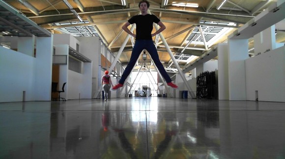
[ElectricSlim] likes taking “Jump Shots” – photographs where the subject is captured in midair. He’s created a novel method to catch the perfect moment with OpenCV and Processing. Anyone who has tried jump shot photography can tell you how frustrating it is. Even with an experienced photographer at the shutter, shots are as likely to miss that perfect moment as they are to catch it. This is even harder when you’re trying to take jump shots solo. Wireless shutter releases can work, but unless you have a DSLR, shutter lag can cause you to miss the mark.
[ElectricSlim] decided to put his programming skills to work on the problem. He wrote a Processing sketch using the OpenCV library. The sketch has a relatively simple logic path: “IF a face is detected within a bounding box AND the face is dropping in height THEN snap a picture” The system isn’t perfect, A person must be looking directly at the camera for the photo the face to be detected. However, it’s good enough to take some great shots. The software is also repeatable enough to make animations of various jump shots, as seen in [ElectricSlim’s] video.
We think this would be a great starting point for a trigger system. Use a webcam to determine when to shoot a picture. When the conditions pass, a trigger could be sent to a DSLR, resulting in a much higher quality frame than what most webcams can produce.
That’s a pretty amazing image to catch peering out from your back balcony. The rig used to record such a gem is seen on the right. It’s called a Barn Door tracker and was built by [DCH972]. Details for this build are scattered all over the place, there’s a video (also found below), another album of some of the best images, and plenty of background info in the Reddit thread.
This design is also know as a Haig or Scotch mount. While we’re dropping links all over the place check out the Wikipedia page on the topic. The point of the system is to move the camera in such a way so that the stars appear to hold in the same place even though the earth is moving. There’s an ATmega32u4 breakout board riding on top of the breadboard. It’s doing some pretty heavy math in order to calculate the stepper motor timing. That’s because the mount is like a photo album, hinged at one side and opened on the other by a ball screw. This linear actuation needs to be meshed with the change in angle of the mounting platform, and finally it needs to sync with the movement of the earth. But once a series of images is captured correctly they can be processed into the composite photograph shown above.
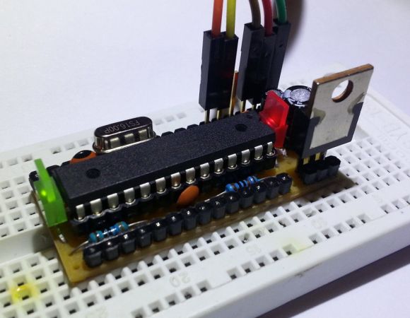
Check out all the stuff crammed into a small swath of strip board. It’s got that characteristic look of a roll-your-own Arduino board, which is exactly what it is. [S. Erisman] shows you how to build your own copy of his YABBS; Yet Another Bare Bones Arduino (on Stripboard).
The strips of copper on the bottom of the substrate run perpendicular to the DIP chip and have been sliced in the middle. This greatly reduces the amount of jumpering that would have been necessary if using protoboard. A few wires make the necessary connections between the two tooled SIL headers that make up the chip socket. On the right hand side there a voltage regulator with smoothing caps. The left side hosts the obligatory pin 13 LED, and the crystal oscillator can be glimpsed on the far side of the ATmega328.
Pin headers along either side of the board have been altered to allow for soldering from the wrong side of the plastic frames. Note that there’s a three-pin hunk that breaks out the voltage regulator, and an ISP programming header sticking out the top to which those female jumper wires are connected.
Ringing in at as little as $2-$4.75 a piece you’ll have no problem leaving this in a project for the long hall. We can’t say the same for a $30+ brand name unit.
Bullet time has been around since at least the first Matrix movie (actually there was a Gap ad before that), and despite it being an oft-used cinematic technique, it still hasn’t gotten old. [Jeremiah] wanted to tap into the awesomeness of bullet time, and managed to come up with a great camera rig using only a GoPro and a ceiling fan.
The build really relies on only two components: a GoPro camera and a ceiling fan. In [Jeremiah]‘s videos, a ceiling fan is mounted between two trees on a sturdy piece of lumber. The GoPro is suspended from one of the fan blades with the help of a piece of wood, a hinge, and a short bit of cable. After [Jeremiah] wired up the fan to a dimmer switch he could control the speed of the fan and Bob’s your uncle.
This isn’t the first time a GoPro has been used for a bullet time rig. In fact, our buddy [Caleb] did a similar build by spinning the camera around on a lazy suzan. Gotta love the high frame rate available on the GoPro, huh?
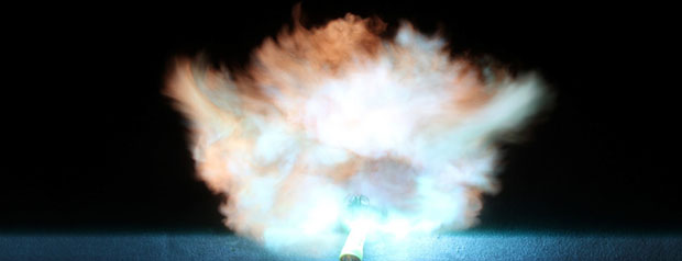
[Patrick] didn’t just want his name in lights. He wanted his name in glowing plasma explosions, made by sending thousands of volts through a very thin wire.
This project is an experiment in capturing high speed images of exploding wires. [Patrick] wanted to know if he could shape wires in such a way that they would explode into letters of plasma. Of course, photographic proof of this would be needed, and would make for an awesome logo in any event.
To get pictures of wire turning into plasma, [Patrick] first needed to construct the necessary electronics. A simple spark gap was constructed on a large plastic cutting board – an excellent high voltage insulator. The huge capacitors are charged with a pair of high voltage transformers, and the entire assembly is triggered with an optocoupler and a very beefy SCR.
Even though [Patrick] designed the system for a low propagation delay, there was still the matter of capturing an exploding wire on film. The camera delay varied by about 120μs, but with a really great camera trigger, [Patrick] eventually got some impressive pictures.
After getting the electronics and photography portion of the build down, [Patrick] turned to making letters out of expanding plasma. Simply shaping the wire into a letter shape before vaporizing it had no effect, so he turned to 3D printed channels to contain the plasma. After a few attempts, this actually worked, allowing him to form the letters L, U, and X in an expanding ball of vaporized wire.